background image

Operating elements

5.1

Display elements isoMED427x-(PT)

After activating the test function (T), all available display elements are shown for 2 seconds.

< | - | >

Identifier for response values

7-segment display

Display of the values

Upper row

R : Insulation resistance
I : Fault current
. : Measuring pulse (flashing)
1 : Relay

% | °C

k | M | 

Ω

A

Measurement units
(°C for isoMED427P-PT only)

on | off

State values

Adr

BS bus address enabled

Relay operating mode

Ω

M

k

C

°

Password protection enabled

5.2

Display in standard mode

If there is no alarm pending, the ON LED is lit and the currently measured values are shown on
the display. The arrow-up/arrow-down buttons can be used to switch between the insulation
resistance value, the percentage load current and the transformer temperature. If the Enter
button is pressed after changing the display, the displayed measurement category remains.

C

°

AL1

AL2

l

AL1

AL2

Ω

k

.

R

AL1

AL2

isoMED427P-PT

16

isoMED427x-(PT)_D00440_00_M_XXDE

Summary of Contents for isoMED427

Page 1: ...isoMED427x PT Insulation monitoring device for medical applications isoMED427x PT _D00440_00_M_XXDE Manual EN...

Page 2: ...me 6 3 cents min mobile phone higher depending on mobile phone tariff Repair service Repair calibration and replacement service Londorfer Strasse 65 35305 Gr nberg Germany Telephone 49 6401 807 780 te...

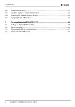
Page 3: ...nd operating messages for each BMS channel 10 4 Mounting and connection 12 4 1 Wiring diagram 13 4 2 Commissioning 14 5 Operating elements 15 5 1 Display elements isoMED427x PT 16 5 2 Display in stand...

Page 4: ...6 10 Resetting the device to factory settings 22 6 11 Querying device information 23 7 Technical data isoMED427 P PT 24 7 1 Factory settings isoMED427x PT 29 7 2 Device overview 30 7 3 Recommended de...

Page 5: ...ach for future reference 1 2 Indication of important instructions and information DANGER Indicates a high risk of danger that will result in death or serious injury if not avoided WARNING Indicates a...

Page 6: ...industry 1 5 Inspection transport and storage Check the shipping and device packaging for transport damage and scope of delivery In the event of complaints the company must be notified immediately se...

Page 7: ...his device For more information on the disposal of Bender devices refer to www bender de Service Support 1 8 Safety If the device is used outside the Federal Republic of Germany the applicable local s...

Page 8: ...th AC 70 264 V In addition the load current and the temperature of the IT system transformer are monitored Alarms and measured values are provided to other bus devices via the BMS interface For displa...

Page 9: ...an only be operated as BMS slave Therefore the alarm indicator and test combination or the respective insulation fault locator take over the master function BMS masters always have BMS address 1 Autom...

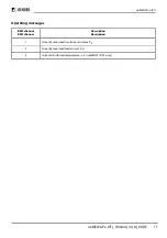
Page 10: ...the transformer the load current and temperature must always be monitored simultaneously Please observe the wiring diagram 3 1 Alarm and operating messages for each BMS channel isoMED427P and isoMED42...

Page 11: ...ages BMS channel BMS channel Description Description 1 Currently measured insulation resistance RF 2 Currently measured load current in 8 Current transformer temperature in C isoMED427P PT only isoMED...

Page 12: ...rules for working on electrical systems must be observed dimensional drawing 36 93 74 5 90 45 70 5 47 5 31 1 DIN rail mounting Snap the rear mounting clip of the device into place in such a way that a...

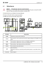
Page 13: ...STW2 N L k AL2 AL1 ON T R MENU A B T2 T1 14 12 11 l Z k Z E KE L1 L2 MK A B EDS A B Terminal Connections E KE Separate connection of E and KE to PE L1 L2 Connection to the IT system to be monitored s...

Page 14: ...connection 4 2 Commissioning Prior to commissioning check proper connection of the ISOMETER Perform a functional test using a genuine earth fault e g via a suitable resistance 14 isoMED427x PT _D0044...

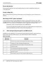
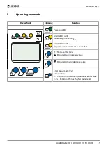
Page 15: ...sponse value Ran Alarm LED 2 is lit Response value I or and C exceeded T Start a self test 2 s Menu item up increase value Menu item down decrease value Start menu mode 2 s Enter button 1 5 s Confirm...

Page 16: ...e values Adr BS bus address enabled Relay operating mode M k C Password protection enabled 5 2 Display in standard mode If there is no alarm pending the ON LED is lit and the currently measured values...

Page 17: ...L2 C AL2 AL1 AL2 AL1 l AL2 AL1 on AL1 AL2 k R AL1 AL2 isoMED427P PT isoMED427 P If different alarms occur simultaneously the display changes at 3 second intervals If several errors occur the respectiv...

Page 18: ...tton to set the appropriate value Confirm with Enter The flashing short symbol R appears 4 The following options are available to exit the menu u Press and hold the Enter button for 2 s to go up one m...

Page 19: ...nitoring response value in A C Set the response value for overtemperature isoMED427P PT only 1 Select N O or N C operation for K1 Adr Setting the BMS address EdS Activate or deactivate automatic insul...

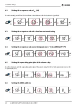
Page 20: ...monitoring 2 s A l A l A l A l 1x k R 2 s 6 4 Setting the response value overtemperature C isoMED427P PT 2 s C C C C 3x R 2 s 6 5 Setting the operating principle of the alarm relay Use this menu to s...

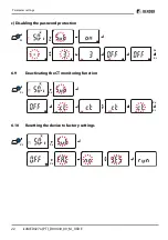
Page 21: ...n be used to enable the password protection change the password or to disable the password protection The password can only be changed if the password protection has been enabled before a Enabling the...

Page 22: ...ng the password protection 2 s 2x off on 5x A k R 2 s 6 9 Deactivating the CT monitoring function 2 s 2x off off on on 5x A k R 2 s 6 10 Resetting the device to factory settings 2x 5x A k R 2 s 22 iso...

Page 23: ...uery the software 1 xx version After activating this function the data will be displayed as scrolling text After completing the routine individual data sections can be selected using the arrow up arro...

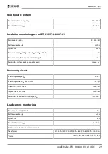
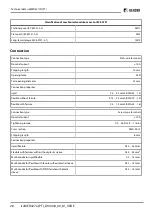
Page 24: ...y III Operating altitude 2000 m AMSL Rated impulse voltage IC1 IC2 3 4 kV IC2 IC3 4 kV Rated insulation voltage IC1 IC2 3 250 V IC2 IC3 250 V Pollution degree 3 Protective separation between IC1 IC2 3...

Page 25: ...e system leakage capacitance Ce max 5 F Measuring circuit Measuring voltage Um 12 V Measuring current Im at RF 0 50 A Internal DC resistance Ri 240 k Impedance Zi at 50 Hz 200 k Permissible extraneous...

Page 26: ...overtemperature 2 s isoMED427P PT Sensor PT100 no series or parallel connections Response value 50 150 C Hysteresis 10 Relative uncertainty 5 Response time overtemperature 5 s Displays memory Display...

Page 27: ...ance under rated operating conditions 10 000 cycles Contact data acc to IEC 60947 5 1 Utilisation category AC 13 AC 14 DC 12 DC 12 DC 12 Rated operational voltage 230 V 230 V 24 V 110 V 220 V Rated op...

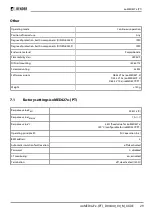
Page 28: ...lexible without ferrule 0 75 2 5 mm2 AWG 19 14 flexible with ferrule 0 2 1 5 mm2 AWG 24 16 Connection type Screw type terminals Nominal current 10 A Tightening torque 0 5 0 6 Nm 5 7 lb in Cross sectio...

Page 29: ...x M4 Software versions D643 V1 0x isoMED427 2 D355 V1 0x isoMED427P 2 D644 V 1 0x isoMED427P PT Weight 150 g 7 1 Factory settings isoMED427x PT Response value Ran 50 k R Response value Ialarm 7 A I R...

Page 30: ...2075301 1 B92075301 2 B72075307 1 B92075307 2 1 Push wire terminal version 2 Screw type terminal version Only this device has a Lloyds Register approval Accessories Description Article number Mounting...

Page 31: ...EDS151 S MK2430 CP9xx CP305 M MK2007 S S Slave M Master 7 4 Standards and certifications The ISOMETER has been developed in compliance with the following standards DIN EN 61557 8 VDE 0413 8 2015 12 Co...

Page 32: ......

Page 33: ......

Page 34: ......

Page 35: ......

Page 36: ...Herausgebers All rights reserved Reprinting and duplicating only with permission of the publisher Bender GmbH Co KG Postfach 1161 35301 Gr nberg Deutschland Londorfer Str 65 35305 Gr nberg Deutschland...

Reviews: