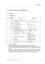
Parameterization via the BMS bus
39
iso1685FR(M)_D00002_02_M_XXEN/06.2017
•
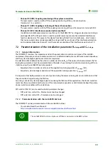
Channel 10 (ANZ): Coupling monitoring of the system connection
This parameter is used to switch off the coupling monitoring of the system connection
(terminals L1/L + and L2/L-).
•
Channel 11 (AER): Coupling monitoring of the earth connection
This parameter is used to switch off the coupling monitoring of the earth connection (terminal E/KE).
•
Channel 12 (SZL): Interference counter (actives method)
In addition to interference detection (see channel 9), the ISOMETER® can trigger a device error during a
prolonged fault.The SZL parameter is used to specify how many consecutive detected interferences
lead to a device error.This prevents the device from being "blind" due to interference - which means
that no measured values can be recorded for a long time.The sensitivity of the interference detection
can be parameterized via channel 9, and the maximum duration of the interference via channel 12.
7.2
Parameterization of the installation parameter R
e-Anlage
and C
e-Anlage
7.2.1 General information
The ISOMETER® monitors the impedance and not the purely ohmic insulation resistance of the installati-
on.However, the purely resistive insulation resistance is also determined by means of the measured impedance
and the system leakage capacitance and can be requested.
In order to be able to determine the ohmic insulation resistance (R
e
) of the network to be monitored, the fol-
lowing two parameters must be parameterized in the order shown during the initial commissioning of the in-
stallation using the iso1685FR tool set provided:
•
Expected ohmic insulation resistance of the application during operation: R
e-Anlage
[kΩ]
•
Expected system leakage capacitance of the application during operation: C
e-Anlage
[nF]
It is important that both parameters are set only once during the commissioning of a new installation and that
they cannot be changed during the lifetime.
Assuming a constant system leakage capacitance during the lifetime of the application, the ohmic insulation
resistance (R
e
) curve, determined by means of the set parameters provides a valid statement about the purely
ohmic insulation condition of the installation.
DIP switch 6 (SS8103) can be used to disable parameter changes.
•
DIP switch 6 is set to ON = Parameters cannot be changed
•
DIP switch 6 is set to OFF = Parameters can be changed
7.2.2 Parameterization with the iso1685FR-Set tool
The ISOMETER® can be parameterized with the iso1685FR-Set tool.
•
You can download the software at:
http://www.bender-de.com/en/service-support/download/software.html
The iso1685FR-Set tool can only be used if there is no master in the BMS system.
Summary of Contents for ISOMETER iso1685FR
Page 6: ...6 ...
Page 10: ...Important information 10 iso1685FR M _D00002_02_M_XXEN 06 2017 ...
Page 14: ...Safety instructions 14 iso1685FR M _D00002_02_M_XXEN 06 2017 ...
Page 42: ...Diagram for the calculation of Ze 42 iso1685FR M _D00002_02_M_XXEN 06 2017 ...
Page 44: ...Information about the measuring method 44 iso1685FR M _D00002_02_M_XXEN 06 2017 ...
Page 50: ...INDEX 50 iso1685FR M _D00002_02_M_XXEN 06 2017 ...
Page 51: ...INDEX 51 iso1685FR M _D00002_02_M_XXEN 06 2017 ...

