background image

49

iso1685FR(M)_D00002_02_M_XXEN/06.2017

INDEX

A

Adresseinstellung


 13

Alarm messages


 34

Alarm relays K1, K2, K3


 17

Anschluss

- Anschlussbedingungen


 23

- Anschlussplan


 26

- Schrittweiser Anschluss


 27

Anzeige


 21

Arbeiten an elektrischen Anlagen


 12

B

Bedienelemente


 21

Bestellangaben


 48

Betriebsmeldungen


 34

BMS bus

- Alarm messages


 34

- Commissioning


 33

- Number of bus nodes


 32

- Protocol


 32

- Setting BMS address


 33

- Slave


 32

- Termination


 31

- Wiring


 31

BMS-Bus

- Betriebsmeldungen


 34

- Master


 33

- Terminierung


 31

- Verdrahtung


 31

Button


 21

C

Commissioning


 28

D

DIP switch


 21

DIP-Schalter-Belegung


 21

E

Error codes


 35

F

Fehlermeldungen zurücksetzen


 36

Firmware update


 36

Functional description


 16

G

Gerätemerkmale


 15

Geräteübersicht


 19

H

History memory


 17

I

Inbetriebnahmeschema


 29

Insulation monitoring


 16

iso1685FR set


 39

K

Kennlinien


 48

M

Maßbild


 19

Measured value transmission


 17

Memory card


 16

 17

 21

Montage des Geräts


 23

N

Normen


 48

O

Operating elements

- Button


 21

- DIP switch


 21

- Memory card


 21

P

Parameterization


 39

- Error handling


 40

Parametrierung

- Fehlerhandling


 40

R

RS-485 interface


 31

RS-485 network

- Correct arrangement


 32

- Terminated network


 31

RS485-Netzwerk

- Falsche Verlegung


 32

- Verdrahtung


 32

S

Selbsttest

- manueller Selbsttest


 19

Self test

- after connection to the supply volta-

ge


 17

Sicherheitshinweise


 12

Software iso1685FR set


 39

T

Technische Daten


 45

Terminating resistor


 31

Terminierung


 13

W

Werkseinstellungen


 43

Z

Zulassungen


 48

Summary of Contents for ISOMETER iso1685FR

Page 1: ... kT IT A B S RS 485 T erm off on CAN1 CAN2 I2 I2 I1 I1 31 32 34 K3 21 22 24 K2 11 12 14 K1 Insulation monitoring device for unearthed AC systems IT systems up to AC 5 kV iso1685FR Software version D0407 V1 1x iso1685FRM with analogue output Software version D0563 V1 0x iso1685FR M _D00002_02_M_XXEN 06 2017 ...

Page 2: ...KG Postfach 1161 35301 Grünberg Germany Londorfer Straße 65 35305 Grünberg Germany Tel 49 6401 807 0 Fax 49 6401 807 259 E Mail info bender de Web www bender de Customer service Service Hotline 0700 BenderHelp Telephone and Fax Carl Benz Straße 8 35305 Grünberg Germany Tel 49 6401 807 760 Fax 49 6401 807 629 E Mail info bender service com ...

Page 3: ...pecific safety information 12 2 4 Address setting and termination 13 2 5 Intended use 13 3 Function 15 3 1 Features 15 3 2 Product description 15 3 2 1 General product description 15 3 2 2 Particularities of the ISOMETER iso1685FRM 15 3 3 Functional description 16 3 3 1 Insulation monitoring 16 3 3 1 1 Active method SSCP 16 3 3 1 2 Passive method 17 3 3 2 Connection monitoring 17 3 3 3 Assignment ...

Page 4: ... Commissioning of the ISOMETER iso1685FRM 30 6 Device communication 31 6 1 Device communication via the BMS bus 31 6 1 1 RS 485 interface with BMS protocol 31 6 1 2 Topology of the RS 485 network 32 6 1 3 BMS protocol 32 6 1 4 Commissioning of an RS 485 network with BMS protocol 33 6 1 5 Setting BMS address 33 6 1 6 Alarm and operating messages via the BMS bus 34 6 1 6 1 Alarm messages 34 6 1 6 2 ...

Page 5: ...D00002_02_M_XXEN 06 2017 8 Diagram for the calculation of Ze 41 9 Information about the measuring method 43 10 Technical data 45 10 1 Tabular data 45 10 2 Factory settings 47 10 3 Standards and certifications 48 10 4 Ordering details 48 ...

Page 6: ...6 ...

Page 7: ...eries which consists of the iso1685FR and iso1685FRM devices This manual is intended for qualified personnel working in electrical engineering and electronics This signal word indicatesthat thereisahighriskofdangerthat will result in electrocution or serious injury if not avoided Thissignalwordindicatesamediumriskofdangerthatcanleadtodeathorseriousinjury if not avoided This signal word indicates a...

Page 8: ...vered Bender devices Extended guarantee for Bender devices which includes an in house repair service or replacement devices at no extra cost Telephone 49 6401 807 780 technical issues 49 6401 807 784 785 sales Fax 49 6401 807 789 E mail repair bender service de Please send the devices for repair to the following address Bender GmbH Repair Service Londorfer Str 65 35305 Grünberg 1 2 3 Field service...

Page 9: ...ender in printed or electronic format 1 5 Storage The devices must only be stored in areas where they are protected from dust damp and spray and dripping water and in which the specified storage temperatures can be ensured 1 6 Disposal Abide by the national regulations and laws governing the disposal of this device Ask your supplier if you are not sure how to dispose of the old equipment The direc...

Page 10: ...Important information 10 iso1685FR M _D00002_02_M_XXEN 06 2017 ...

Page 11: ...nd regulations must be complied with The European standard EN 50110 can be used as a guide Only qualified personnel are permitted to carry out the work necessary to install commis sion and run a device or system Risk of electrocution due to electric shock Touching live parts of the system carries the risk of An electric shock Damage to the electrical installation Destruction of the device Before i...

Page 12: ...cted from the IT system for the duration of the test In order to check the correct connection of the device a functional test has to be carried out before starting the system In the event of an alarm message of the ISOMETER the insulation fault should be eliminated as quickly as possible IftheISOMETER isinstalledinsideacontrolcabinet theinsulationfaultmessagemustbeau dible and or visible to attrac...

Page 13: ...equipment in order to adapt it to local equipment and operating conditions Please heed the limits of the range of application indicated in the technical data Any use other than that described in this manual is regarded as improper Unspecified frequency range When connecting to an IT system with frequency components below the specified frequency range the response times and response values may diff...

Page 14: ...Safety instructions 14 iso1685FR M _D00002_02_M_XXEN 06 2017 ...

Page 15: ...uration iso1685FRM RS 485 interface BMS bus and Modbus RTU switched using the DIP switch The BMS bus is used to output measured values and to configure the device Modbus RTU is used to communicate with the Modbus analogue converter M 7024 By means of the converter the iso1685FRM provides an analogue output μSD card with data logger and history memory for alarms Protection against unauthorized or a...

Page 16: ...me needed until the maximum file size is reached is approximately 1 day Hence a μSD card with a memory space of 2 Gbytes can record data for approx 800 days When the maximum data limit is reached on your card the oldest file in each case will be overwritten If the card cannot be written to despite an inserted μSD card a device error occurs With this fault relay K3 31 32 34 is not switched If no μS...

Page 17: ...ssignment of the alarm relays K1 K2 K3 Alarm relay K1 switches when the value falls below the response value Zan insulation impedance Alarm relay K2 switches when the value falls below the response value Zan insulation impedance Alarm relay K3 switches in the event of a device error or a connection fault If the passive method is enabled then the relays also switch Alarm relay K1 switches when the ...

Page 18: ...3 s the normal measurement mode begins If a device error is detected the corresponding alarm will be signalled via the BMS bus as well as via the alarm relay K3 31 32 34 This relay continuously operates in N C mode i e it de energises even in case of a complete device failure During this self test which occurs during device start up the alarm relays K1 and K2 are not swit ched 3 5 2 Continuous sel...

Page 19: ...2_02_M_XXEN 06 2017 4 Device overview 4 1 Dimensions SERVICE ALARM 2 ISOMETER iso1685 ON ALARM 1 PGH ON 246 mm 125 mm 40 5 mm 40 75 mm 51 mm 368 mm 383 mm 401 5 mm 106 mm 64 mm 8 75 mm 5 2 mm 61 8 mm 76 6 mm 39 8 mm 55 7 mm ...

Page 20: ...RM BMS Modbus RTU k I kT IT no function 31 32 34 Relay output for device er ror Service LED 21 22 24 Relay output for Alarm insu lation fault 11 12 14 Relaiy output for Alarm insu lation E KE Connection earth reference Connect both to PE A1 A2 Supply voltage DC24V Abritrary polarity SERVICE ALARM 2 ISOMETER iso1685 ON ALARM 1 PGH ON LEDs ON Operation flashes PGH ON No function SERVICE Device error...

Page 21: ...hanged OFF Parameter can be changed 7 Device error notification when the μSD card has not been inserted ON Device error will be signalled The device error relay K3 31 32 34 does not switch OFF Device error will NOT be signalled 8 Not used DIP switch number Function 1 Switching between BMS Modbus RTU protocols ON Modbus RTU OFF BMS 2 5 Setting BMS address 6 Locking the parameter function ON Paramet...

Page 22: ...nd connection error system earth Lights continuously Also refer to the list of error codes on page 31 ALARM 1 yellow Insulation fault Lights continuously when the insulation impedance falls below the response value Ze Zan2 Passive methodLights continuously when the voltage UN PE exceeds the set response value Uan überschreitet UN PE Uan ALARM 2 yellow Insulation fault 2 alarm Lights continuously w...

Page 23: ...he protective earth conductor PE Risk of injury from sharp edged terminals Risk of lacerations Touch the enclosure and the terminals with due care Risk of property damage due to unprofessional installation If more than one insulation monitoring device is connected to a conductively connected system the system can be damaged If several devices are connected the device does not functionanddoesnotsig...

Page 24: ...e into consideration that an insulation fault can only be detected correctly when the rectifier valves carry a minimum current of 10 mA All terminals are pluggable push wire terminals Solid connecting wires can be directly pluggedin Forconnectionofflexiblecables the push wire terminals mustbepushedopenby pressing the corresponding orange interlocking mechanism with a flat head screwdriver ...

Page 25: ...odbus RTU ISOMETER iso 1685FR iso1685FRM SERVICE ALARM 2 ISOMETER iso1685 ON ALARM 1 PGH ON L1 L2 L3 N US 6A K1 K3 K2 313234 111214 212224 Thyristor control 1 8 1 1 8 8 Heating elements CVD reactor DC 24 V 6A 3 N AC 5 kV 50 60 Hz PE 1A 1A BMS master 2 L1 PE k I kT IT 300 V tap I2 I2 I1 I1 A1 A2 E KE L2 L1 A B S ...

Page 26: ...13234 111214 212224 Thyristor control 1 8 1 1 8 8 Heating elements CVD reactor DC 24 V 6A 3 N AC 5 kV 50 60 Hz PE 1A 1A L1 PE k I kT IT 300 V tap I2 I2 I1 I1 mA 4 20 mA A1 A2 E KE L2 L1 A B S ICP CON M 7024 Iout0 20 1 10 11 Iout1 Iout2 INIT Y DATA G DATA R Vs B GND Y DATA G DATA R Vs B GND Iout3 AGND Iout0 AGND AGND Vout3 Vout2 Vout1 Vout0 DC power supply 1 24 V 0 5 A 24 V GND DC power supply 2 24...

Page 27: ...2 34 device error for external signalling The relay outputs 11 12 14 and 21 22 24 are implemented redundantly Terminal Socket Connections I2 I2 Digital input currently has no function I1 I1 Digital input currently has no function A B S Connection to BMS bus RS 485 S shielded internally connected to PE terminating switch RS 485 Term Modbus RTU connection iso1685FRM only k l kT lT No function 31 32 ...

Page 28: ...int of the system to be monitored 5 Connect terminal L2 to L1 300 V tap of the system to be monitored 6 Connect terminal A1 A2 to DC 24 V 7 Connect the signal outputs 11 12 14 and 21 22 24 Insulation fault alarm for the active and passive methods and 31 32 34 device error for external signalling The relay outputs 11 12 14 and 21 22 24 are implemented redundantly 5 3 Commissioning Refer to chapter ...

Page 29: ...voltage Switch on mains voltage No Yes ja ja iso1685FR not suitable Connection fault or device error check the connections Should factory settings be kept No Make the settings via the BMS bus Are the alarm LEDs lighting No Yes The set response value is too low adjustment required Function test with a suitable ohmic resistance between the system and earth Value 50 of the response value Zan Yes No C...

Page 30: ... Converter M7024 and to GND of DC power supply 1 Switch on supply voltage Switch on mains voltage No Yes Yes Yes iso1685FRM is not suitable Connection fault or device error check the connections Should factory settings be kept No Yes Make the settings via the BMS bus Are the alarm LEDs lighting No Yes The set response value is too low adjustment required Function test with a suitable ohmic resista...

Page 31: ...ped with the terminating switch RS 485 Term off on An RS 485 network that is not terminated is likely to become unstable and may result in malfunctions Only the first and last device in one line may be terminated Stub feeders in the network if any must not be terminated The length of the stub feeders is restricted to 1 meter Abb 6 1 Wiring and termination of the BMS bus with the device housing A1A...

Page 32: ... restricted to 32 devices If more devices are to be connected Bender provides a DI 1DL repeater 6 1 3 BMS protocol This protocol is an essential part of the Bender measuring device interface BMS bus protocol Data transmissi on generally makes use of ASCII characters Interface data are Baud rate 9600 baud Transmission 1 start bit 7 data bits 1 parity bit 1 stop bit 1 7 E 1 Parity even Checksum Sum ...

Page 33: ...the bus lines A defective device is connected to the bus Terminating resistors are not activated or connected 6 1 4 Commissioning of an RS 485 network with BMS protocol Interconnect terminals A and B of all bus devices in one line Switch the terminating resistors on at the start and the end of the RS 485 network If a device at the end of the bus is not terminated connect a 120 Ω resistor to termin...

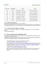
Page 34: ... earth 8 Voltage UN PE response value Uan Passive measuring method Overtemperature coupling terminal L1 10 Temperature of the coupling L1 150 C Overtemperature coupling terminal L2 11 Temperature of the coupling L2 150 C Alarm Channel Meaning Insulation impedance Ze kΩ 1 Insulation impedance response value Zan System leakage capacitance Ce nF 2 Leakage capacitance Ce in nF Insulation resistance Re...

Page 35: ...ly voltage 12 V Replace device 8 44 Hardware Supply voltage 12 V Replace device 8 45 Hardware Supply voltage 5 V Replace device 8 46 Hardware Supply voltage 3 3 V Replace device 8 47 Hardware Hardware Replace device 8 51 Hardware Monitoring the hardware temperature Replace device 8 52 Hardware Monitoring the sensor temperature Replace device 9 61 Parameter calibration value Insulation measurement ...

Page 36: ... chapter ISOMETER s iso1685FRM DIP switch assignment The wiring connection diagram for the ISOMETER iso1685FRM and Modbus analog converter can be found under chapter 5 2 3 Anschlussplan mit Modbus RTU ISOMETER iso1685FRM The connection is also described in chapter chapter 5 2 5 Step by step connection of the iso1685FRM ISOMETER For further information regarding commissioning refer to chapter 5 3 2...

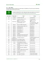
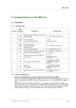
Page 37: ...fferent insulation conditions of the installation Channel BMS comman d Description Setting range 1 Ze kO Response value for insulation measurment active method 10 1000 Default 25 Step size 1 2 Ce instal lation nF Ce value nF Fixed System leakage capacitance 1 200 Default 1 Step size 1 3 Re instal lation kO Re value kΩ Fixed System insulation fault Good condition 10 500 Default 180 Step size 1 4 MP...

Page 38: ...ing of the L conductor connection Service parameters Channel 8 EWL Uan V Response offset voltage UN PE passive method This parameter defines the response threshold for the passive measurement method In the case of unsymmetric insulation faults on one or more phases an offset voltage develops between the star point of the IT network and earth If the offset voltage UN PE exceeds the set response val...

Page 39: ... determined by means of the measured impedance and the system leakage capacitance and can be requested In order to be able to determine the ohmic insulation resistance Re of the network to be monitored the fol lowing two parameters must be parameterized in the order shown during the initial commissioning of the in stallation using the iso1685FR tool set provided Expected ohmic insulation resistanc...

Page 40: ...gain b Ohmic insulation resistance of the installation is LOWER than the parameterized value Output Re Re 1 MΩ Error handling Re_Anlage and Ce_Anlage must be parameterized again Incorrect parameterization of Ce_Anlage Consequences The resulting ohmic insulation resistance value does not correspond to the expected value of the installation Error cases a System leakage capacitance of the installatio...

Page 41: ... 06 2017 8 Diagram for the calculation of Ze The following formula for calculating the insulation value measured by ISOMETER is applicable for Ze 200 kΩ 0 5 10 15 20 25 0 50 100 150 200 250 iso1685FRM M 7024 kΩ mA Ze kΩ Ia mA 4 200 16 ...

Page 42: ...Diagram for the calculation of Ze 42 iso1685FR M _D00002_02_M_XXEN 06 2017 ...

Page 43: ... Monitoring PE coupling E KE switched off Useful default settings Active methodResponse value 25 kΩ Measuring buffer depth 4 Passive methodResponse value 200 V Interference detection Degree of interference 20 Number of interferences until a device error 6 120 ms Important When interference detection is switched off the shutdown time of the active method is somewhat lon ger for phase faults because...

Page 44: ...Information about the measuring method 44 iso1685FR M _D00002_02_M_XXEN 06 2017 ...

Page 45: ...ible extraneous DC voltageUfg 0 V Permissible system leakage capacitance Ce 200 nF Response values for insulation monitoring active method Response value Zan Alarm 10 1000 kΩ 25 kΩ Relative uncertainty 100 kΩ 1 MΩ acc to IEC 61557 8 2007 01 15 Relative uncertainty 10 100 kΩ 5kΩ 15 Response time tan for measurementbuffer size MPT 3 150 ms Hysteresis 25 Response values for insulation monitoring pass...

Page 46: ...0 2 A 0 1 A Minimum contact rating 1 mA atAC DC 10V Connection via terminals except system coupling Connection type pluggable push wire terminals Connection rigid flexible 0 2 2 5 mm2 0 2 2 5 mm2 Connection flexible with connector sleeve without with plastic sleeve 0 25 2 5 mm2 Conductor sizes AWG 24 12 Connection of the system coupling Connection type pluggable push wire terminals Connection rigi...

Page 47: ...er Software Value Condition can be set via Insulation measurement response value Zan Active method 25 kΩ BMS Leakage capacitance of the installation Ce Anlage 1 nF BMS Insulation resistance of the installation Re Anlage 180 kΩ BMS Measured data buffer size for Ze active method 4 BMS Offset voltage response value Uan passive method 125 V BMS Response value of measured value suppression Interference...

Page 48: ...61557 8 VDE 0413 8 IEC 61557 8 IEC 61326 2 4 DIN EN 60664 1 VDE 0110 1 EN 50178 1998 04 10 4 Ordering details The data labelled with an are absolute values Type Response value range Nominal voltage Supply voltage Communication Art No iso1685FR 525 10 kΩ 1000 kΩ AC 0 400 V DC 18 30 V BMS B91065800 iso1685FRM 525 10 kΩ 1000 kΩ AC 0 400 V DC 18 30 V BMS Modbus RTU B91065804 ...

Page 49: ...n zurücksetzen 36 Firmware update 36 Functional description 16 G Gerätemerkmale 15 Geräteübersicht 19 H History memory 17 I Inbetriebnahmeschema 29 Insulation monitoring 16 iso1685FR set 39 K Kennlinien 48 M Maßbild 19 Measured value transmission 17 Memory card 16 17 21 Montage des Geräts 23 N Normen 48 O Operating elements Button 21 DIP switch 21 Memory card 21 P Parameterization 39 Error handlin...

Page 50: ...INDEX 50 iso1685FR M _D00002_02_M_XXEN 06 2017 ...

Page 51: ...INDEX 51 iso1685FR M _D00002_02_M_XXEN 06 2017 ...

Page 52: ...ender GmbH Co KG Postfach 1161 35301 Grünberg Germany Londorfer Straße 65 35305 Grünberg Germany Tel 49 6401 807 0 Fax 49 6401 807 259 E Mail info bender de www bender de Fotos Bender archiv BENDER Group ...

Reviews: