Settings
Settings
iso685-D-B_D00177_05_M_XXEN/07.2017
34
10.1
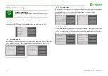
(1.3) Profile
Adapt the area of application of the ISOMETER® to your system profile. For a description
of the profiles, refer to
The following can be selected:
10.1
(1.4) System type
Adapt the ISOMETER® to the IT system to be monitored. The following can be selected:
10.1
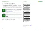
1.5
ISOnet
Make the settings to use the ISONet function.
The ISOnet function ensures via the Ethernet connection that
only
one
ISOMETER® of the
interconnection is active when several ISOMETER®s are connected to an IT system.
For further information regarding the ISOnet function, refer to
.
•Power circuits
Suitable for most IT systems.
•Control circuits
Not recommended for voltages > 230 V.
•Generator
Fast measuring times, fast fault location possible.
•High capacitance
Suitable for system with high leakage capacitances.
•Inverter > 10 Hz
Suitable for systems with dynamic frequency control by
inverters in the range 10…460 Hz.
•Inverter < 10 Hz
Suitable for systems with extremely low frequency control
in the range 1…460 Hz.
•DC
DC system
(refer to
“Connection to a DC system” on page 20
•AC
Single-phase AC system
(refer to
“Connection to an AC system” on page 19
)
•3AC
3AC system
(refer to
“Connection to a 3(N)AC system” on page 19
)
10.1
1.5.1
ISOnet
Activate or deactivate the ISOnet function
10.1
1.5.2
Number of devices
Configure the number of devices (2…20) in a subsystem.
10.1
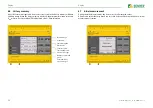
(1.6) Device
Set the ISOMETER® insulation resistance measurement function to active or inactive:
10.1
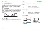
(1.7) T(Start)
The ISOMETER® can be operated with a start-up delay of 0…120 seconds. The start-up is
delayed until the initial measurement takes place.
10.1
(1.8) Coupling monitoring
The ISOMETER® continuously monitors the coupling of energised systems. The coupling
of de-energised systems is monitored at 8-hour intervals. This monitoring function can be
activated or deactivated.
•off
The ISOnet is deactivated
•BCOM
The ISOnet function is activated via BCOM
•Active
The device is active.
•Inactive
The device DOES NOT measure the insulation resistance, the
message
Device inactive
appears on the display. The
IT system is NOT being monitored!
•on
Coupling monitoring is activated.
•off
Coupling monitoring is deactivated.


