background image

Important information

48

isoHV425_D00082_03_M_XXEN/05.2020

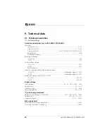
Switching elements

Switching elements................................................................................. 2 x 1 N/O contacts, common terminal 11
Operating principle .................................................................... N/C operation/N/O operation (N/O operation)*
Electrical endurance, number of cycles ................................................................................................................ 10,000
Contact data acc. to IEC 60947-5-1:

Utilisation category .......................................................................................  AC-12AC-14 DC-12 DC-12 DC-12
Rated operational voltage........................................................................................ 230 V230 V24 V110 V220 V
Rated operational current ................................................................................................. 5 A2 A 1 A 0.2 A 0.1 A
Minimum contact rating  .................................................................................................. 1 mA at AC/DC 

 10 V

Environment/EMC

EMC .......................................................................................................................................... IEC 61326-2-4, EN 50121-3-2
Ambient temperatures:

Operation ................................................................................................................................................... -40…+70 ºC
Transport .................................................................................................................................................... -40…+85 ºC
Storage ........................................................................................................................................................ -40…+70 ºC

Classification of climatic conditions acc. to IEC 60721:

Stationary use (IEC 60721-3-3).................................3K23 (except condensation and formation of ice)
for W variant.................................................................................................................................................................3K24
Transport (IEC 60721---2) ......................................... 2K11 (except condensation and formation of ice)
Long-term storage (IEC 60721-3-1).......................1K22 (except condensation and formation of ice)

Classification of mechanical conditions acc. to IEC 60721:

Stationary use (IEC 60721-3-3) .......................................................................................................................... 3M11
for W variant............................................................................................................................................................... 3M12
Transport (IEC 60721-3-2) ...................................................................................................................................... 2M4
Long-term storage (IEC 60721-3-1) ............................................................................................................... 1M12

Connection

Connection type...................................................................................................................................... push-wire terminal
Nominal current ................................................................................................................................................................. ≤10 A
Cross section ...........................................................................................................................................................AWG 24 –14
Stripping length ............................................................................................................................................................... 10 mm
Rigid........................................................................................................................................................................0.2…2.5 mm

2

Flexible without ferrules ............................................................................................................................  0.75…2.5 mm

2

Flexible with ferrules with/without plastic sleeve  ........................................................................  0.25…2.5 mm

2

Multi-conductor flexible with TWIN ferrules with plastic sleeve.................................................0.5…1.5 mm

2

Opening force .......................................................................................................................................................................  50 N
Test opening, diameter............................................................................................................................................... 2.1 mm

Summary of Contents for ISOMETER isoHV425

Page 1: ...ith AGH422 coupling device Insulation monitoring device for unearthed AC AC DC and DC systems IT systems up to 3 N AC AC 1000 V Software version D0453 V1 xx isoHV425 D4 4 D0500 V1 xx isoHV425 D4M 4 isoHV425_D00082_02_M_XXEN 05 2020 ...

Page 2: ...berg Germany PO Box1161 35301 Grünberg Germany Tel 49 6401 807 0 Fax 49 6401 807 259 E mail info bender de www bender de Bender GmbH Co KG All rights reserved Reprinting only with permission of the publisher Subject to change Photos Bender archive ...

Page 3: ... 10 2 2 Work activities on electrical installations 10 2 3 Intended use 11 3 Function 12 3 1 Device features 12 3 2 Functional description 12 3 2 1 Monitoring of the insulation resistance 13 3 2 2 Undervoltage overvoltage monitoring 14 3 2 3 Self test error codes 14 3 2 4 Signalling assignment of the alarm relays K1 K2 16 3 2 5 Measuring and response times 17 3 2 6 Password protection on OFF 18 3 ...

Page 4: ...soHV425 D4 4 31 5 4 5 Analogue output isoHV425 D4M 4 31 5 5 t menu time configuration 32 5 6 SEt menu function configuration 32 5 7 Measured value display and history memory 33 6 BMS protocol isoHV425 D4 4 34 7 Modbus RTU protocol isoHV425 D4 4 35 7 1 Reading out the Modbus register from the ISOMETER 35 7 1 1 The master sends a command to the ISOMETER 35 7 1 2 The ISOMETER answers the master 35 7 ...

Page 5: ...Table of contents 5 isoHV425_D00082_03_M_XXEN 05 2020 8 IsoData data string isoHV425 D4 4 45 9 Technical data 46 9 1 Tabular presentation 46 9 2 Standards 51 9 3 Ordering information 51 INDEX 52 ...

Page 6: ...elow This manual is intended forqualified personnel working in electrical engi neering and electronics DANGER This signal word indicates that there is a high risk of danger that will result in death or serious injury if not avoided WARNING This signal word indicates a medium risk of danger that can lead to death or serious injury if not avoided CAUTION This signal word indicates a low level risk t...

Page 7: ...rt bender service com 1 2 2 Repair Service Repair calibration update and replacement service for Bender products Repair calibration testing and analysis Hardware and software update Delivery of replacement devices for faulty or incorrectly delivered Bender devices Extended warranty for Bender devices with in house repair service or replace ment devices at no extra cost Telephone 49 6401 807 780 te...

Page 8: ...y For software products the Softwareklausel zur Überlassung von Standard Software als Teil von Lieferungen Ergänzung und Änderung der Allgemeinen Lieferbedingun gen für Erzeugnisse und Leistungen der Elektroindustrie software clause in respect of the licensing of standard software as part of deliveries modifications and changes to general delivery conditions for products and services in the electr...

Page 9: ...ore the rules and regulations that apply for ac cident prevention at the place of use must be observed 1 7 Disposal Abide by the national regulations and laws governing the disposal of this device Ask your supplier if you are not sure how to dispose of the old equipment The directive on waste electrical and electronic equipment WEEE directive and the di rective on the restriction of certain hazard...

Page 10: ...e is being used in a location outside the Federal Republic of Germany the applicable local standards and regulations must be complied with European standard EN 50110 can be used as a guide DANGER Risk of electrocution due to electric shock Touching live parts of the system carries the risk of An electric shock Damage to the electrical installation Destruction of the device Before installing and co...

Page 11: ...ust be ad justed to local equipment and operating conditions by means of customised parameter settings Please heed the limits of the range of application indicated in the technical da ta Any use other than that described in this manual is regarded as improper Only qualified personnel are permitted to carry out the work necessary to install commission and run a device or system To ensure that the I...

Page 12: ...nt unauthorised parameter changes isoHV425 D4 4 RS 485 galvanically separated including the following protocols BMS interface Bender measuring device interface for data exchange with other Bender components Modbus RTU IsoData for continuous data output isoHV425 D4M 4 Analogue output galvanically separated 3 2 Functional description The ISOMETER measures the insulation resistance RF and the system ...

Page 13: ...Us is interrupted The device function can be tested using the test button T Parameters are assigned to the device via the LCD and the control buttons on the front panel this function can be password protected Parameterisation is also possible via the BMS bus for example by using a BMS Ethernet gateway COM465IP or Modbus RTU 3 2 1 Monitoring of the insulation resistance The two parameters R1 and R2...

Page 14: ...mit value has been deactivated The alarm will be deleted when the limit values plus hysteresis see Page 29 are no longer violated 3 2 3 Self test error codes The isoHV425xx contains test routines for checking that the device is functioning cor rectly during operation Some test routines are performed cyclically or continuously in the background during the normal measuring function Other test routin...

Page 15: ...n error The connection of terminals E or KE to earth is interrupted Action Check connection eliminate error The error code will be erased automatically once the error has been eliminated E 02 System connection error The internal resistance of the system is too high the connection of terminals L1 or L2 to the system is interrupted or L1 and L2 are connected with reversed polarity to the monitored D...

Page 16: ... system connection check a system voltage Un nega tive DC 100 VDC is applied to the ISOMETER the message E 02 for a system connec tion with reversed polarity is also displayed If these test functions are started via a test button or the communication interface this can be indicated not only by the LEDs AL1 and AL2 lighting up but also by the message test via the relays menu out Signalling assignme...

Page 17: ...he insulation resistance RF and the system leakage capacitance Ce Response delay ton The response delay ton is set uniformly for all messages in the t menu using the param eter ton whereby each alarm message specified in the signalling assignment has its own timer for ton This delay time can be used for interference suppression in the case of short measuring times An alarm will only be signalled w...

Page 18: ...be reset via the interface Only one ISOMETER may be controlled via an external test reset button A galvanic parallel connection of several test or reset inputs for testing multiple insulation moni toring devices is not allowed 3 2 9 Fault memory The fault memory can be activated or deactivated with the parameter M in the out menu When the fault memory is activated all pending alarm messages of the...

Page 19: ...this mode is not possible and no addi tional transmitter may be connected to the RS 485 bus cable The ASCII data string for the ISOMETER is described on Page 45 The parameter address baud rate and parity for the interface protocols are configured in the out menu 3 2 12 Analogue interface isoHV425 D4M 4 The following functions can be selected at the potential free analogue signal output Voltage out...

Page 20: ...ualified personnel are permitted to carry out the work necessary to install commission and run a device or system DANGER Risk of electrocution due to electric shock Touching live parts of the system carries the risk of An electric shock Damage to the electrical installation Destruction of the device Before installing and connecting the device make sure that the installation has been de energised O...

Page 21: ... 05 2020 Dimension diagram sketch for screw mounting push wire terminal connection All dimensions in mm The front plate cover can be opened at the lower part marked with an arrow 93 45 67 5 36 31 1 47 5 74 5 2 2 1 2 3 Click 2 x 1 x 100 107 Click M4 M4 ...

Page 22: ...m 4 2 1 Connection isoHV425 D4 4 US KE A1 A2 Test Reset Up 6 A 6 A L1 L2 PE L3 Up E E GND AK2 AK1 AK1 GND AK2 L2 L1 ON T R MENU AL1 AL2 k ISOMETER isoHV425 AK1 AK2 GND Up KE A1 A2 14 24 11 A T R B R on off 14 24 11 K1 K2 COM465IP RS 485 A B R T R AGH422 AK2 AK1 GND E E UP L1 L2 ...

Page 23: ...etails about the conductor cross sections required for wiring refer to the technical data fromPage 46 US KE A1 A2 Test Reset Up 6 A 6 A L1 L2 PE L3 Up E E GND AK2 AK1 AK1 GND AK2 L2 L1 ON T R MENU AL1 AL2 k ISOMETER isoHV425 AK1 AK2 GND Up KE A1 A2 14 24 11 M T R M 14 24 11 K1 K2 T R AGH422 AK2 AK1 GND E E UP L1 L2 M M V ...

Page 24: ...ely to PE The same wire cross section as for A1 A2 is to be used L1 L2 Connection to the IT system to be monitored Up AK1 GND AK2 Connect the terminals of the AGH422 to the corresponding terminals of the ISOME TER T R Connection for the external combined test and reset button 11 14 Connection to alarm relay K1 11 24 Connection to alarm relay K2 A B RS 485 communication interface with connectable t...

Page 25: ...turbances the pulse symbol will be hidden 3 Start a manual self test by pressing the test button T Whilst the test but ton is pressed and held down 1 5 s all display elements available for this device are shown During the test the tES symbol flashes Any internal mal functions detected are displayed as error codes see Page 14 The alarm relays are not checked during the test factory setting The sett...

Page 26: ...igation and settings Up and down button Navigate up or down in the menu settings Increase or decrease values MENU Pressing the MENU enter button for more than 1 5 s Start menu mode or If the device is already in menu mode Exit menu item Esc Any recent changes will not be stored Pressing the MENU enter button for less than 1 5 s Confirm menu selection or Confirm modified value The areas of the disp...

Page 27: ...m voltage Un R Insulation resistance RF C System leakage capacitance Ce 2 Monitored conductor 3 Voltage type DC Voltage type AC 4 Measured values and units 5 Password protection is enabled 6 In the menu mode the operating mode of the respective alarm relay is displayed 7 Communication interface With measured value isoData operation 8 The fault memory is enabled 9 Condition symbols 10 Identifier fo...

Page 28: ...lay times and self test cycles SEt Set device control parameters InF Query software version HiS Query and clear the history memory ESC Go to the next higher menu level 1s 1s 1s P1 Pn ESC 1 5s 1 5s AL out t SEt InF HiS ESC R kΩ C μF U L1 L2 V UL1 V UL2 V R UR kΩ or t 5 Min 1s k R 1 5s 1s 1 5s 1 5s Measured value display Menu selection Parameter input Password optional Value input Value saved ...

Page 29: ...he parameters U and U for monitoring the system voltage Un can be activated or deactivated The maximum undervoltage val ue is limited by the overvoltage value FAC Factory setting Cs Customer settings 5 4 out menu 5 4 1 Configuration of the relay operating mode FAC Factory setting Cs Customer settings Display Activation Setting value Description FAC Cs Value range FAC Cs R1 on R2 500 50 kΩ Prewarni...

Page 30: ...r settings LED off LED flashes LED on 5 4 3 Fault memory configuration FAC Factory setting Cs Customer settings K1 r1 K2 r2 LEDs Description Display FAC Cs Display FAC Cs ON AL1 AL2 off on Device error E xx r1 R1 Ω on r2 R1 Ω off Prewarning R1 Fault RF at L1 r1 R1 Ω on r2 R1 Ω off Prewarning R1 Fault RF at L2 r1 R2 Ω off r2 R2 Ω on Alarm R2 Fault RF at L1 r1 R2 Ω off r2 R2 Ω on Alarm R2 Fault RF a...

Page 31: ...even parity 1 stop bit 8o1 8 data bits odd parity 1 stop bit 8n1 8 data bits no parity 1 stop bit Display Setting value Description FAC Value range FAC Cs U 0 10 V I 4 20 mA I 0 20 mA I 0 400 μA U 0 10 V U 0 10 V I 4 20 mA 4 20 mA load 130 Ω I 0 20 mA 0 20 mA load 130 Ω I 0 400 μA 0 400 μA load 3 kΩ U 0 10 V 0 10 V load 20 kΩ AnA R xxx kΩ on 120 kΩ 120 kΩ Scaled value for the displayed non linear ...

Page 32: ...nge FAC Cs t 0 10 0 s Start up delay at device start ton 0 99 0 s Response delay K1 and K2 toff 0 99 0 s Delay on release K1 and K2 test OFF 1 24 24 h Repetition time device test Display Activation Setting value Description FAC Cs Value range FAC Cs off 0 999 0 Password for parameter setting nEt on Test of the system connection L1 L2 during device test S Ct on Device test during device start FAC R...

Page 33: ... value is indicated in the history memory HiS Display Description R kΩ Insulation resistance RF 1 kΩ 4 MΩ Resolution 1 kΩ C μF System leakage capacitance Ce 1 μF 200 μF Resolution 1 μF U L1 L2 V System voltage L1 L2 Un 0 VRMS 1 15 kVRMS Resolution 1 VRMS U L1 V Residual voltage L1 PE UL1e 0 VDC 1 15 kVDC Resolution 1 VDC U L2 V Residual voltage L2 PE UL2e 0 VDC 1 15 kVDC Resolution 1 VDC R Fault l...

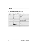
Page 34: ...terface BMS bus protocol Data is transferred using ASCII characters BMS channel no Operation value Alarm 1 RF Prewarning R1 2 RF Alarm R2 3 Ce 4 Un Undervoltage 5 Un Overvoltage 6 Connection error earth E 01 7 Connection error system E 02 8 All other device errors E xx 9 Fault location 10 UL1e 11 UL2e 12 Update counter 13 RFU 14 15 ...

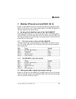
Page 35: ... to the ISOMETER In the following example the master addresses the ISOMETER with address 3 and re quests the contents of register 1003 The register contains the channel description of measuring channel 1 7 1 2 The ISOMETER answers the master 7 2 Writing to Modbus registers parameter setting Registers in the device can be modified with the Modbus command 0x10 set multiple registers Parameter regist...

Page 36: ...de 0x10 Byte 2 3 Start register 0x0BBB Byte 4 5 Number of registers 0x0001 Byte 6 Number of data bytes 0x02 Byte 7 8 Data 0x0002 Byte 9 10 CRC16 Checksum 0x9F7A Byte Name Example Byte 0 ISOMETER Modbus address 0x03 Byte 1 Function code 0x10 Byte 2 3 Start register 0x0BBB Byte 4 5 Number of registers 0x0001 Byte 6 7 CRC16 Checksum 0x722A Exception code Description 0x01 Impermissible function 0x02 I...

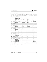
Page 37: ...value Device error Without alarm Alarm 1 Alarm 2 1000 1003 RF Insulation fault 71 no alarm RF Insulation fault 1 prewarning RF Insulation fault 1 alarm Connection earth 102 device error 1004 1007 1008 1011 Un Voltage 76 no alarm Un Undervoltage 77 alarm Un Overvoltage 78 alarm System con nection 101 device error 1012 1015 Ce Capacitance 82 no alarm 1016 1019 UL1e Voltage 76 no alarm 1020 1023 UL2e...

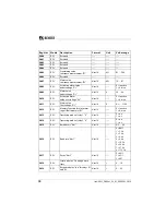
Page 38: ... 30 U 3010 RW Activation alarm value overvoltage U Uint16 0 Inactive 1 Active 3011 RW Alarm value Overvoltage U Uint16 V U 1100 3012 RW Memory function for alarm mes sages fault memory M Uint16 0 Inactive 1 Active 3013 RW Operating mode of relay 1 r1 Uint16 0 n o 1 n c 3014 RW Operating mode of relay 2 r2 Uint16 0 n o 1 n c 3015 RW Bus address Adr Uint16 0 3 90 3016 RW Baud rate Adr 1 Uint16 0 BMS...

Page 39: ... assignment of relay 1 r1 Uint16 Bit 9 Bit 1 Chapter 7 5 3 3028 RW Signalling assignment of relay 2 r2 Uint16 Bit 9 Bit 1 Chapter 7 5 3 8003 WO Factory settings for all parameters Uint16 0x6661 fa 8004 WO Factory settings only for parame ters resettable by FAC Uint16 0x4653 FS 8005 WO Start device test Uint16 0x5445 TE 8006 WO Clear fault memory Uint16 0x434C CL 9800 9809 RO Device names Uint16 AS...

Page 40: ...annel is shown with the example of channel 1 7 5 2 1 Float Floating point value of the channels Representation of the bit order for processing analogue measured values according to IEEE 754 S Sign E Exponent M Mantissa Word 0x00 0x01 0x02 0x03 0x08 0x09 10 words in total Each word contains two ASCII characters 1000 1001 1002 1003 HiByte LoByte HiByte LoByte HiByte LoByte HiByte LoByte Floating poi...

Page 41: ...re reserved The complete byte is calculated from the sum of the alarm type and the test type Bit 7 6 5 4 3 2 1 0 Meaning External test Internal test Reserved Reserved Reserved Alarm Error Alarm type X X X X X 0 0 0 No alarm X X X X X 0 0 1 Prewarning 0 0 X X X 0 1 0 Device error X X X X X 0 1 1 Reserved X X X X X 1 0 0 Warning X X X X X 1 0 1 Alarm X X X X X 1 1 0 Reserved X X X X X Reserved X X X...

Page 42: ...the range of validity Bit 7 6 5 4 3 2 1 0 Meaning Unit 0 0 0 0 0 Invalid init 0 0 0 0 1 No unit 0 0 0 1 0 Ω 0 0 0 1 1 A 0 0 1 0 0 V 0 0 1 0 1 0 0 1 1 0 Hz 0 0 1 1 1 Baud 0 1 0 0 0 F 0 1 0 0 1 H 0 1 0 1 0 C 0 1 0 1 1 F 0 1 1 0 0 Second 0 1 1 0 1 Minute 0 1 1 1 0 Hour 0 1 1 1 1 Day 1 0 0 0 0 Month Range of validity 0 0 X X X X X X Actual value 0 1 X X X X X X The actual value is lower 1 0 X X X X X ...

Page 43: ... writing any value 1 x Err Device error E xx 2 rx R1 Ω Prewarning R1 fault RF at L1 3 rx R1 Ω Prewarning R1 fault RF at L2 4 rx R2 Ω Alarm R2 fault RF at L1 5 rx R2 Ω Alarm R2 fault RF at L2 6 rx U V Alarm message Un undervoltage 7 rx U V Alarm message Un overvoltage 8 rx test Manually started self test 9 rx S AL Device start with alarm 10 Reserved When reading always 0 When writing any value 11 R...

Page 44: ... error 145 0x91 Own address Value Description of parameters 1023 0x3FF Parameter measured value invalid The menu item of this parameter is not displayed 1022 0x3FE No measured value no message 1021 0x3FD Measured value parameter inactive 1020 0x3FC Measured value parameter only temporarily inactive e g while transmitting a new parameter Indication in the menu 1019 0x3FB Parameter measured value va...

Page 45: ... unknown DC 1234 Residual voltage UL1e VDC 1234 Residual voltage UL2e VDC 123 Insulation fault location 100 100 1234 5 Approximate unsymmetrical insulation resistance RFU kΩ 1234 Alarm message hexadecimal without leading 0x The alarms are included in this value with the OR function Assignment of the alarms 0x0002 Device error 0x0004 Prewarning insulation resistance RF at L1 0x0008 Prewarning insul...

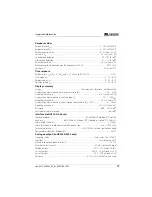
Page 46: ...on degree 3 Protective separation reinforced insulation between IC2 IC3 4 overvoltage category III 300 V IC3 IC4 overvoltage category III 300 V Voltage tests routine test acc to IEC 61010 1 IC2 IC3 4 AC 2 2 kV IC3 IC4 AC 2 2 kV Supply voltage Supply voltage Us AC 100 240 V DC 24 240 V Tolerance of Us 30 15 Frequency range Us 47 63 Hz Power consumption 3 W 9 VA IT system being monitored Nominal sys...

Page 47: ...isplay range measured value system voltage Un 30 1 15 kVRMS Operating uncertainty 5 at least 5 V Display range measured value system leakage capacitance at RF 20 kΩ 0 200 μF Operating uncertainty 15 at least 2 μF Password off 0 999 0 off Fault memory alarm messages on off Interface isoHV425 D4 4 only Interface protocol RS 485 BMS Modbus RTU isoData Baud rate BMS 9 6 kbit s Modbus RTU selectable is...

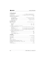
Page 48: ...climatic conditions acc to IEC 60721 Stationary use IEC 60721 3 3 3K23 except condensation and formation of ice for W variant 3K24 Transport IEC 60721 2 2K11 except condensation and formation of ice Long term storage IEC 60721 3 1 1K22 except condensation and formation of ice Classification of mechanical conditions acc to IEC 60721 Stationary use IEC 60721 3 3 3M11 for W variant 3M12 Transport IEC...

Page 49: ...Measuring circuit IC1 L1 L2 Control circuit IC2 AK1 GND AK2 Up E Rated voltage 1000 V Overvoltage category III Rated impulse voltage IC1 IC2 8 kV Rated insulation voltage IC1 IC2 1000 V Pollution degree 3 Protective separation reinforced insulation between IC1 IC2 Overvoltage category III 1000 V IT system being monitored System voltage range Un AC0 1000 V DC 0 1000 V Tolerance of Un AC 10 DC 10 Me...

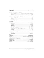
Page 50: ... Cross section AWG 24 14 Stripping length 10 mm Rigid 0 2 2 5 mm2 Flexible without ferrules 0 75 2 5 mm2 Flexible with ferrules with without plastic sleeve 0 25 2 5 mm2 Multi conductor flexible with TWIN ferrules with plastic sleeve 0 5 1 5 mm2 Opening force 50 N Test opening diameter 2 1 mm Single cables for terminals Up AK1 GND AK2 requirement for connecting cables between isoHV425xx and AGH422 ...

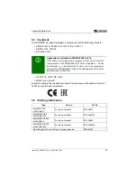
Page 51: ...cation in rail vehicles DIN EN 45545 2 2016 If the distance to neighbouring components that do not meet the requirements of the DIN EN 45545 2 Table 2 standard is 20 mm horizontally or 200 mm vertically these are to be regarded as grouped See DIN EN 45545 2 Chapter 4 3 Grouping rules Standards approvals and certifications Type Version Art No isoHV425 D4 4 with AGH422 Push wire terminal B71036501 i...

Page 52: ...18 Functional description 12 H History memory 18 33 How to use this manual 6 I Interface protocols 19 IsoData 19 Data string 45 M Malfunction 16 Measuring times 17 Menu AL 29 out 29 SEt 32 t 32 Overview 28 Modbus register assignment 37 Modbus RTU 19 Monitoring for undervoltage and overvoltage 14 insulation resistance R mode 13 Mounting and connection 20 O Operating time 17 Operation 26 Ordering in...

Page 53: ..._XXEN 05 2020 S Safety instructions 10 Self test 14 Setting time delays 33 SignallingassignmentofthealarmrelaysK1 K2 16 Start up delay t 17 T Technical data 46 Total response time 17 W Work activities on electrical installations 10 ...

Page 54: ...berg Deutschland Tel 49 6401 807 0 Fax 49 6401 807 259 E Mail info bender de www bender de Fotos Bender Archiv All rights reserved Reprinting and duplicating only with permission of the publisher Subject to change Bender GmbH Co KG PO Box 1161 35301 Grünberg Germany Londorfer Str 65 35305 Grünberg Germany Tel 49 6401 807 0 Fax 49 6401 807 259 E Mail info bender de www bender de Photos Bender Archi...

Reviews: