Important information
37
isoHV425_D00082_03_M_XXEN/05.2020
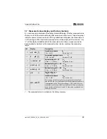
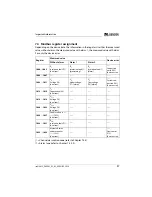
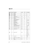
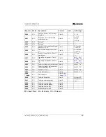
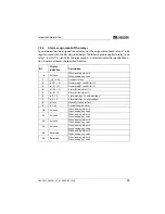
7.4 Modbus register assignment
Depending on the device state, the information in the registers is either the measured
value without alarm, the measured value with alarm 1, the measured value with alarm
2 or only the device error.
( ) = Channel description code (refer to
[ ] = Alarm type (refer to Chapter 7.5.2.2)
Register
Measured value
Device error
Without alarm
Alarm 1
Alarm 2
1000…1003
R
F
Insulation fault (71)
[no alarm]
R
F
Insulation fault (1)
[prewarning]
R
F
Insulation fault (1)
[alarm]
–––
Connection
earth (102)
[device error]
1004 …1007
–––
–––
–––
–––
1008 …1011
U
n
Voltage (76)
[no alarm]
U
n
Undervoltage
(77) [alarm]
U
n
Overvoltage
(78) [alarm]
–––
System con-
nection (101)
[device error]
1012 …1015
C
e
Capacitance (82)
[no alarm]
–––
–––
–––
1016 …1019
U
L1e
Voltage (76)
[no alarm]
–––
–––
–––
1020 …1023
U
L2e
Voltage (76)
[no alarm]
–––
–––
–––
1024 …1027
Fault location in %
––– (1022)
[no alarm]
–––
–––
–––
1028 …1031
R
FU
Insulation fault (71)
[no alarm]
–––
–––
–––
1032 …1035
Measured value
update counter
––– (1022)
[no alarm]
–––
–––
–––
Device error
(115)
[device error]


