28
isoUG425_D00220_00_Q_DEEN / 04.2016
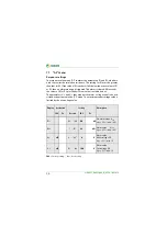
FAC
= Factory setting;
Cs
= User setting
:
LED off
:
LED blinking
:
LED on
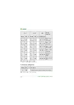
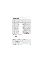
Fault memory configuration
FAC
= Factory setting;
Cs
= User setting
r1
+R2 < Ω
off
r2
+R2 <Ω
on
Alarm R2
Error
R
F
on L+
r1
-R2 < Ω
off
r2
-R2 < Ω
on
Alarm R2
Error
R
F
on L-
r1
U < V
off
r2
U < V
on
Alarm
U
nDC
Undervoltage
r1
U > V
off
r2
U > V
on
Alarm
U
nDC
Overvoltage
r1
test
off
r2
test
off
Device test
manually
started
r1
S.AL
off
r2
S.AL
off
Device start with
alarm
Display
FAC
Cs
Description
M
off
Memory function for alarm messages (Fault memory)
K1
"
r1
"
K2
"
r2
"
LEDs
Message
description
Display
FAC
Cs
Display
FAC
Cs
ON AL1 AL2
Summary of Contents for ISOMETER isoUG425
Page 18: ......


