background image

Quickstart


EN

LG_D00393_00_Q_XXEN / 

12.

2020

LifeGuard® 

LG

2

-

Series

Protection Panels

Summary of Contents for LifeGuard LG2 Series

Page 1: ...Quickstart EN LG_D00393_00_Q_XXEN 12 2020 LifeGuard LG2 Series Protection Panels ...

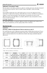
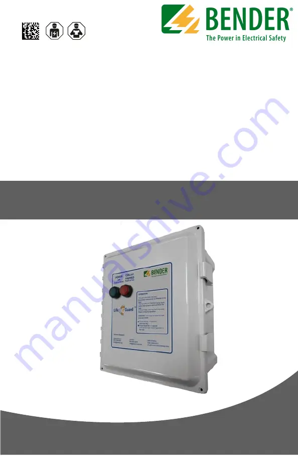
Page 2: ...onsibility is assumed by Bender for any consequences arising from use of this document Use of this document This quick start applies to standard LifeGuard models with lighted push button front panels as pictured above as well as open panels with no enclosure Standard model Installation Mounting NEMA 4X Polycarbonate Enclosure enclosure code P The standard enclosure for LifeGuard protection panels ...

Page 3: ...ssional electrician licensed in accordance with local laws and regulations must perform this installation The enclosure must be penetrated in order to bring the line and load conductors to the protective circuit Bender recommends making these penetrations on the bottom of the enclosure and the use of NEMA 4X minimum fittings to maintain the environmental rating of the enclosure The specifics of th...

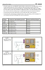
Page 4: ...d wires to the ground lug on the backplate Do not route the ground wire through the current transformer Voltage Conductors not including ground Referenced Wiring Diagram 120VAC 1ph 2w L1 N FigureW1 208VAC 3ph 3w L1 L2 L3 FigureW2 208 120VAC 3ph 4w L1 L2 L3 N FigureW3 240 120VAC 1ph 3w L1 L2 N FigureW4 480VAC 3ph 3w L1 L2 L3 FigureW2 480 277VAC 3ph 4w L1 L2 L3 N FigureW3 600VAC 3ph 3w L1 L2 L3 Figu...

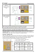
Page 5: ...be mounted in a location sufficient to protect live electrical equipment Use four 10 screws for mounting It should be placed X inches away from other equipment This vertical clearance X minimum depth of enclosure measured from the installed backplate of the backplate is 7L4 5L3 3L2 1L1 8T4 6T3 4T2 2T1 Note 1 Note 1 B D A C CT Type A x B C x D 100 A 8 25 x 10 25 210 x 260 8 88 x 10 88 225 x 276 100...

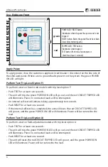
Page 6: ...green POWER ON LED will go out and the red CIRCUIT TRIPPED LED will illuminate Power to connected loads will be interrupted Push RESET for at least one second The unit will reset the red CIRCUIT TRIPPED LED will go out and the green POWER ON LED will illuminate Power will be restored to the load green POWER LED RESET button Illuminates when the panel has power and is not tripped RESET button Reset...

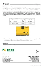
Page 7: ...el option A have field adjustable ground fault current trip level and trip time The factory defaults are 30 mA and 0 s These models have a CTUB101 CTBC35P current sensor which has a three position potentiometer that must be set to the correct position depending on the RCMA420 D 2 ground fault current trip setting For trip settings up to 100 mA the potentiometer must be rotated to the left position...

Reviews: