System description
10
3.1.3
Mechanical design
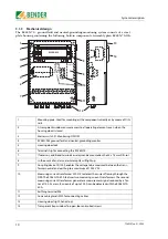
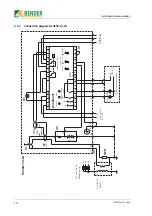
The RC48N-70... ground-fault and neutral-grounding monitoring system consists of a steel
plate housing containing the following built-in components. Assembly plan RC48N-70-10A:
1
Mounting plate: Used for mounting all the components directly or by means of DIN-
rails.
2
A transparent window ensures access to all operating elements even when the
housing door is closed.
3
Master switch S1: Monitoring ON/OFF
4
RC48N-935 ground-fault and neutral-grounding monitor
5
Housing door lock
6
Terminal strip for connecting the RC48N-70...
7
If necessary, additional terminals or relays can be mounted on the 35 x 7.5 mm DIN-rail.
8
In the event of an alarm, alarm lamp H3 will light up
9
Coupling device CD1000 enables the voltage to be measured between the trans-
former neutral and earth up to a maximum of 1000 V AC.
10
Measuring current transformer W0-S15 to detect the current flowing through the
NER. The RC48N-70-50A features two measuring current transformers. The second
measuring current transformer generates a measurement signal reduced by a fac-
tor of 100. As a result, currents of up to 100 A can be detected with the RC48N-70-
50A.
11
Earthing terminal M6
12
Cone cable glands M20 for connecting cables
13
Housing door (right-hand stop)
14
Transparent trap window. To open, loosen knurled screws.
ON
OFF
ALARM
RC48N-935
CD1000
-X1
8
9
10
11
13
12
1
2
3
4
5
6
7
14
W0-S15
W0-S15
Summary of Contents for RC48N-70-10 A
Page 4: ...Table of Contents 4 TGH1397en 11 2006...
Page 16: ...Installation and connection 16 TGH1397en 11 2006...
Page 20: ...Operation and configuration 20 TGH1397en 11 2006...
Page 24: ...INDEX 24 TGH1397en 11 2006...
Page 25: ......


