16
To
ECU/
Modulator
Valve
Power
Cable
ECU Side
Trailer
Side
To
Nose
Box
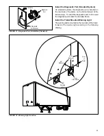
FIGURE 19 - Inline Power Connector
ABS
ABS
5 Pin
Weatherpack
One Bayonett Connector
at Relay Valve
Diagnostic
Male
Bayonet
Warning
Light
Chassis
Ground
J560
6" Pigtail
Two
Speed
Sensors
Road Side
Road Side
5 Pin
Weatherpack
Deutsch
Hd-10
Diagnostic
Bayonett Connector
at Relay Valve
(Up to 2)
Male
Bayonet
Warning
Light
Chassis
Ground
J560
6" Pigtail
Speed
Sensor
(2 or 4)
BASIC
STANDARD
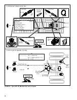
FIGURE 20 - Standard and Basic ABS Harnesses
Install the Inline Power Connector
The inline power connector is on the end of the main ABS
harness and connects the ABS system to the trailer
electrical system.
Install the Main ABS Harness
1. Remove power from the trailer.
2. Unlock the ECU cover and remove.
3. Install the ECU connectors as follows:
Standard: Plug the grey harness connector into the
ECU connector labeled “X1”. The connector is keyed
and can only fit in one direction. Plug the black harness
connector into the ECU connector labeled “X2”. This
connector is also keyed.
Basic: Plug the green harness connector into the ECU
connector labeled “X1”. This connector is also keyed
and is the only connector on the ECU.
4. Install the ECU cover by first engaging the alignment
tabs and then hinging the cover closed, ensuring that
the convoluted tubing is captured in the strain relief slots.
Slide the cover lock to the locked position. An optional
tie wrap may be used to lock the cover in place.
5. Route harness to designated locations. Make sure that
the harness is properly routed and secured to prevent
damage to the harness.


