4
AIR DRYER AND RESERVOIR SYSTEM
OPERATION:
GENERAL
The Bendix
®
AD-IS
®
air dryer and reservoir system
alternates between two modes or “cycles” during operation:
the
Charge Cycle
and the
Purge Cycle.
The following
describes these “cycles” of operation.
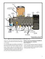
CHARGE CYCLE
(Refer to Figure 2.)
When the compressor is running loaded (compressing air),
compressed air fl ows through the compressor discharge
line to the inlet (1/IN) port of the air dryer body. The
compressed air often includes contaminates such as oil,
oil vapor, water, and water vapor.
Traveling through the discharge line and into the air dryer,
the temperature of the compressed air falls, causing
some of the contaminants to condense and drop to the
bottom of the air dryer and purge valve assembly
.
These
contaminants are ready to be expelled at the next purge
cycle.
The air then fl ows into the desiccant cartridge,
where it fl ows through an oil separator—or coalescing fi lter
if equipped with a PuraGuard
®
oil coalescing cartridge—
which removes water in liquid form as well as liquid oil and
solid contaminants.
Air then fl ows into the desiccant drying bed and becomes
progressively more dry as water vapor adheres to the
desiccant material in a process known as adsorption.
Dry air exits the desiccant cartridge, through the center of
the base assembly, then fl ows to the delivery check valve
and through an orifi ce and into the purge reservoir. The
delivery check valve opens, supplying air to the pressure
protection valves (A) through (D) simultaneously, the
safety valve, and also to the reservoir port of the attached
governor. The purge reservoir fi lls, storing air that will be
used to regenerate the desiccant during the purge cycle.
This air is available to supply downstream components
during the charge mode.
When the air pressure reaches approximately 106 psi, the
four pressure protection valves will open and air will be
supplied to the primary reservoir, secondary reservoir, and
accessories. If the pressure protection valves are preset
to different values the valves will open—in order of lowest
setting to highest setting—when charging a fl at system.
The air dryer and purge reservoir will remain in the charge
cycle until the air brake system pressure builds to the
governor cut-out setting of approximately 130 psi.
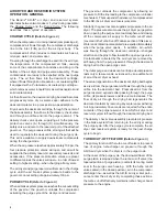
PURGE CYCLE
(Refer to Figure 3.)
When air brake system pressure reaches the cut-out setting
of the governor, the governor unloads the compressor
activating the purge cycle of the air dryer and reservoir.
The governor unloads the compressor by allowing air
pressure to fi ll the line leading to the compressor unloader
mechanism. This suspends the delivery of compressed air
to the AD-IS
®
air dryer and reservoir system.
Similarly, the governor also supplies air pressure to the air
dryer. The pressure also moves the air dryer purge piston
down, opening the purge valve to atmosphere and closing
off the compressor air supply to the turbo cut-off valve
(covered in the Turbo Cut-off Feature section of this piece).
Water and contaminants captured are expelled immediately
when the purge valve opens. In addition, air—which
was fl owing through the desiccant cartridge—changes
direction and begins to fl ow toward the open purge valve.
Contaminants collected by the air dryer are removed by
air fl owing from the purge reservoir through the desiccant
drying bed to the open purge valve.
The initial purge and desiccant cartridge decompression
lasts only a few seconds, evidenced by an audible burst
of air at the air dryer exhaust.
The actual regeneration of the desiccant drying bed begins
as dry air from the purge reservoir fl ows through the purge
orifi ce into the desiccant bed. Pressurized air from the
purge reservoir expands after passing through the purge
orifi ce; its pressure lowers and its volume increases. The
fl ow of dry air through the drying bed regenerates the
desiccant material by removing any water vapor adhering
to it. Approximately 30 seconds are required for the entire
contents of the purge reservoir of an AD-IS air dryer and
reservoir system to fl ow through the desiccant drying bed.
The delivery check valve assembly prevents air pressure
in the brake system from returning to the air dryer during
the purge cycle. After the purge cycle is complete, the air
dryer and reservoir system is ready for the next charge
cycle to begin.
TURBO CUT-OFF FEATURE
(Refer to Figure 3.)
The primary function of the turbo cut-off valve is to prevent
loss of engine turbocharger air pressure through the
AD-IS
air dryer when the dryer is in the purge mode.
At the onset of the purge cycle, the downward travel of the
purge piston is stopped when the turbo cut-off valve (the
tapered portion of purge piston) contacts its mating metal
seat in the purge valve housing. With the turbo cut-off
valve seated (in the closed position), air in the compressor
discharge line—as well as the AD-IS air dryer inlet port—
cannot enter the air dryer. By completing these actions,
the turbo cut-off effectively maintains turbo charger boost
pressure to the engine.


