2
After exiting the end cover, the air flows into the desiccant
cartridge where an oil separator, located between the outer
and inner shells of the cartridge, removes water in liquid
form as well as liquid oil and solid contaminants.
After exiting the oil separator, air enters the space between
the desiccant drying bed and the outer cartridge shell and
flows down through the column of desiccant. Flowing through
the desiccant column, air becomes progressively dryer as
water vapor adheres to the desiccant material in a process
known as “ADSORPTION.” Using the adsorption process,
the desiccant cartridge typically removes 95% of the water
vapor from the pressurized air.
Dry air exits the bottom of the desiccant cartridge through
its center opening and returns to the air dryer body
assembly. As air flows through the supply cavity it is also
conducted, via internal passages, to the non-serviceable
purge control mechanism contained in the body. The purge
control mechanism (not shown) is able to monitor supply
air pressure. The air then flows through the delivery check
valve assembly and out the delivery port to the first (supply)
reservoir of the air system. As air moves past the delivery
check valve, on its way to the delivery port, it is also
conducted to the purge control mechanism. The purge
control mechanism is able to monitor air brake system
pressure as well as supply air pressure.
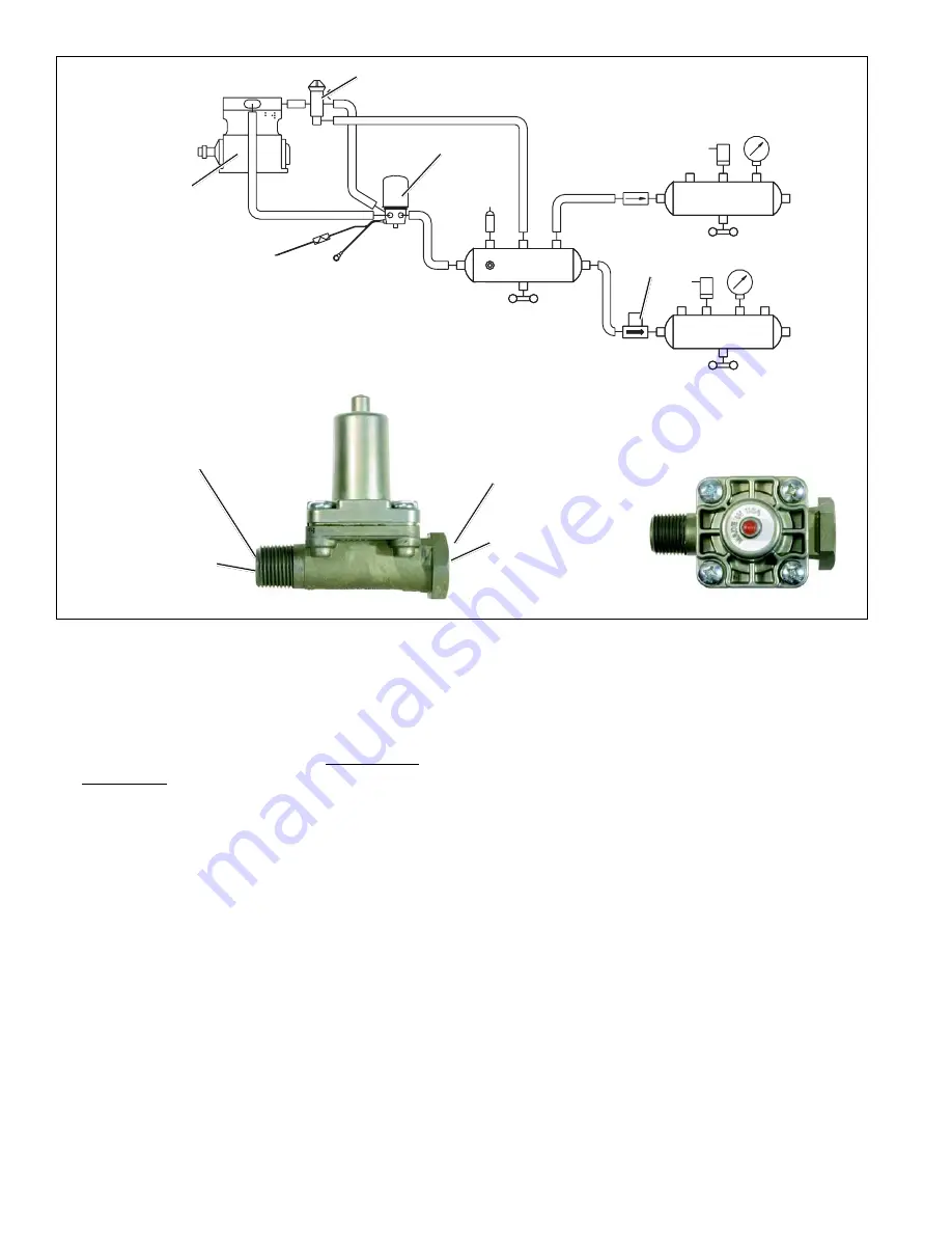
FIGURE 2 - AD-SP
™
AIR DRYER SYSTEM DRAWING WITH EXTERIOR AND TOP VIEW OF SC-PR
™
VALVE.
FRONT AXLE
AD-SP
™
AIR
DRYER
COMPRESSOR
GOVERNOR
REAR AXLE
SUPPLY
SC-PR
™
VALVE
DELIVERY PORT
(TO FRONT SERVICE
RESERVOIR)
EMBOSSED PORT
IDENTIFICATION “2 DEL”
EMBOSSED PORT
IDENTIFICATION
“1 SUP”
SUPPLY PORT
(FROM SUPPLY
RESERVOIR)
OPERATION
GENERAL
The AD-SP
™
air dryer alternates between two operational
modes or “cycles” during operation: the Charge Cycle and
the Purge Cycle. The following description of operation is
separated into these “cycles” of operation.
CHARGE CYCLE
(refer to Figure 3)
When the compressor is loaded (compressing air)
compressed air, along with oil, oil vapor, water and water
vapor flows through the compressor discharge line to the
supply port of the air dryer body.
Air entering the supply port immediately encounters the
“turbo cut-off” valve. With no air pressure in the control port,
the turbo cut-off piston moves the valve away from its seat
in the body allowing the supply air to enter the body. As air
travels through the end cover assembly, its direction of flow
changes several times, reducing the temperature, causing
contaminants to condense and drop to the bottom or sump
of the air dryer body.


