10
9. Install the balance piston spring (5) in the unloader
piston (7), then install the small diameter of the balance
piston (4) through the center of the spring.
10. Install the unloader cover gasket (3) on the cylinder
head making certain the unloader vent passage and
both screw holes align.
11. Position the unloader cover (2) on top of the balance
piston (4) making certain the stamped logo is visible.
12. Press and hold the unloader cover (2) in place on
the cylinder head and install both unloader cover cap
screws (1). Torque the cover cap screws (1) from 62
to 71 inch pounds (7-8 Nm).
INSTALLING THE COMPRESSOR
1. If the compressor was removed for replacement, install
the drive components.
Torque the crankshaft nut to
220 - 254 foot pounds (210-290 Nm).
2. Install any supporting bracketing on the compressor in
the same position noted and marked during removal.
3. Install the gasket on the drive flange of the compressor.
Make certain oil supply or return holes in the gasket
are properly aligned with the compressor and engine.
Gasket sealants are not recommended. Secure the
compressor on the engine and tighten the mounting
bolts.
4. Install the discharge, inlet and governor adapter fittings,
if applicable, in the same position on the compressor
noted and marked during disassembly. Make certain
the threads are clean and the fittings are free of
corrosion. Replace as necessary. See the Torque
Specifications for various fitting sizes and types of
thread on page 11 of this manual.
5. Inspect all air, oil, and coolant lines and fittings before
reconnecting them to the compressor. Make certain
o-ring seals are in good or new condition. Tighten all hose
clamps.
6. Clean oil supply line. Before connecting this line to the
compressor. Run the engine briefly to be sure oil is
flowing freely through the supply line.
7. Before returning the vehicle to service, perform the
Operation and Leakage Tests specified in this manual.
Pay particular attention to all lines reconnected during
installation and check for air, oil, and coolant leaks
at compressor connections. Also check for noisy
operation.
TESTING REBUILT COMPRESSOR
In order to properly test a compressor under operating
conditions, a test rack for correct mounting, cooling,
lubricating, and driving the compressor is necessary. Such
tests are not compulsory if the unit has been carefully rebuilt
by an experienced person. A compressor efficiency or
build up test can be run which is not too difficult. An engine
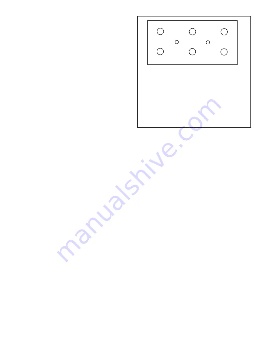
Sequence Torque
(Nm)
1 . . . . . . . . . . . 13
2 . . . . . . . . . . . 13
3 . . . . . . . . . . . 20
4 . . . . . . . . . . . 20
5 . . . . . . . . . . . 20
6 . . . . . . . . . . . 20
7 . . . . . . . . . . . 20
8 . . . . . . . . . . . 20
lubricated compressor must be connected to an oil supply
line of at least 15 psi. pressure during the test and an oil
return line must be installed to keep the crankcase drained.
Connect to the compressor discharge port, a reservoir with
a volume of 1500 cubic inches, including the volume of the
connecting line. With the compressor operating at 2100
RPM., the time required to raise the reservoir(s) pressure
from 85 psi to 100 psi should not exceed 5 seconds. During
this test, the compressor should be checked for gasket
leakage and noisy operation, as well as unloader operation
and leakage. If the compressor functions as indicated
reinstall on the vehicle connecting all lines as marked in
the disassembly procedure.
BA-922
®
COMPRESSOR SPECIFICATIONS
Typical weight ................................................................. 60 lbs.
Number of cylinders ............................................................... 2
Bore Diameter ...................................... 3.622 in. (95.005 mm)
Stroke ................................................... 2.125 in. (53.970 mm)
Calculated displacement at 1250 RPM .................... 31.7 CFM
Flow Capacity @ 1800 RPM & 120 PSI ..................... 25.2 CFM
Flow Capacity @ 3000 RPM & 120 PSI ..................... 38.4 CFM
Maximum recommended RPM ................................ 3000 RPM
Minimum coolant flow maximum RPM ............... 2.0 Gals./Min.
Approximate horsepower required:
Loaded 1800 RPM at 120 PSIG ................................... 8.73 HP
Unloaded 1800 RPM .................................................... 1.96 HP
Maximum inlet air temperature ........................................ 170°F
Maximum discharge air temperature ............................... 350°F
Minimum oil pressure required ....................................... 15 PSI
Minimum oil-supply line size ...................................... 3/16" I.D.
Minimum unloader-line size ....................................... 3/16" I.D.
Minimum Governor Cutout Pressure ............................. 120 PSI
Sequence Torque
(Nm)
9 . . . . . . . . . . . 32
10 . . . . . . . . . . 32
11 . . . . . . . . . . 32
12 . . . . . . . . . . 32
13 . . . . . . . . . . 32
14 . . . . . . . . . . 32
15 . . . . . . . . . . 13
16 . . . . . . . . . . 13
FIGURE 10 -
BA-922
®
COMPRESSOR HEAD BOLT TORQUE
SEQUENCE.
5, 11
3, 9
8, 14
6, 12
4, 10
7,13
1, 15
2, 16


