background image

2

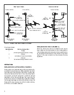
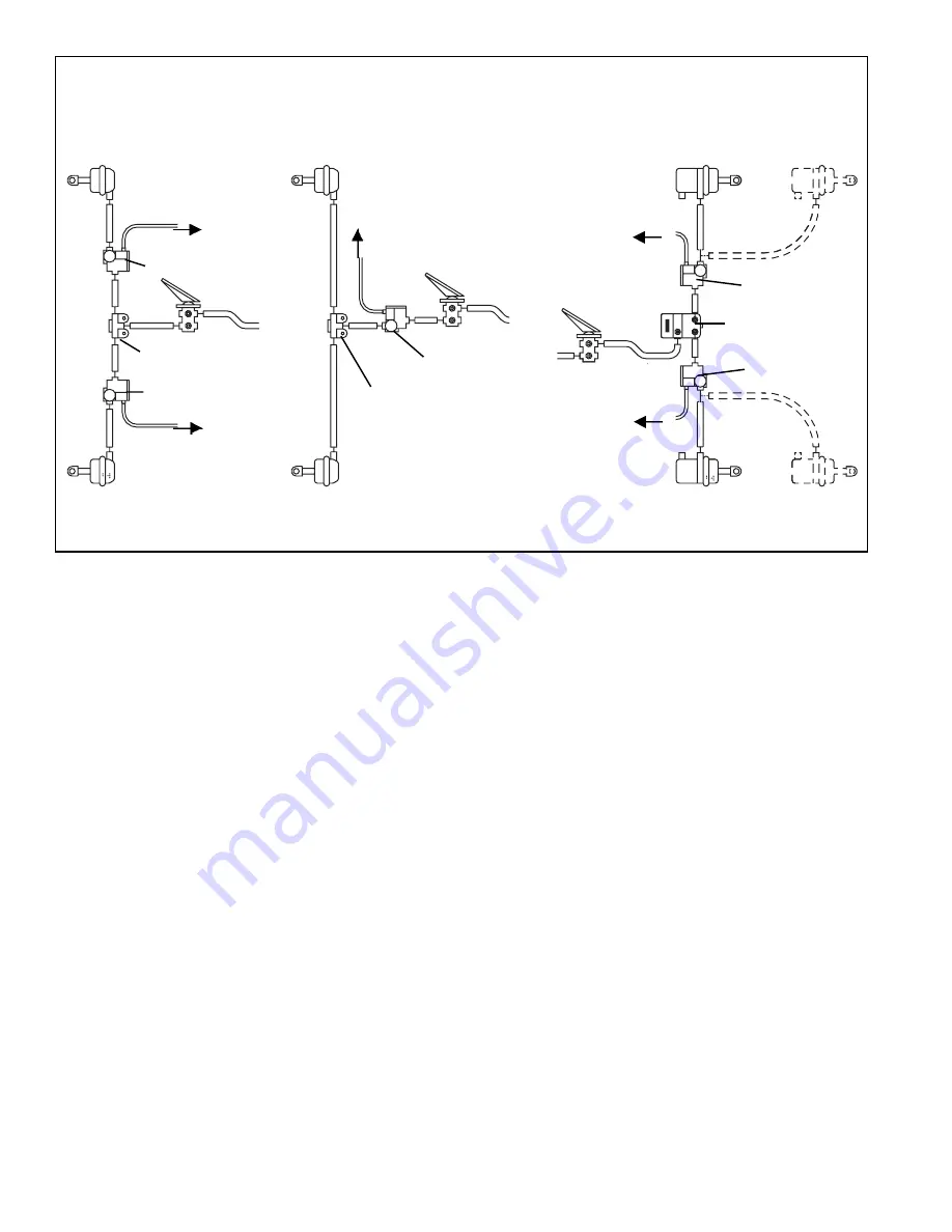
FIGURE 2 - 

WHEEL AND AXLE CONTROL SYSTEMS

bw

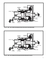
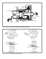
NON-ANTILOCK HOLD (FIGURE 4)

When the desired air pressure is attained in the service
brake chambers, the brake system is in the holding position.
In the holding position both solenoids in the modulator remain
de-energized and the balance of the internal components
remain in the same position as they assumed during
application.

REAR AXLE SYSTEM

FRONT AXLE SYSTEMS

AXLE CONTROL

WHEEL CONTROL

WHEEL CONTROL

SERVICE BRAKE

CHAMBER

M-21

 OR M-22

 MODULATOR

M-21

 OR M-22

 MODULATOR

QUICK RELEASE VALVE

M-21

 OR M-22

 MODULATOR

SERVICE BRAKE

CHAMBER

SERVICE &

SPRING BRAKE

CHAMBER

QUICK RELEASE VALVE

TO

ANTILOCK

CONTROLLER

CONTROLLER/

RELAY ASSEMBLY

M-21

 OR M-22

MODULATOR

M-21

 OR M-22

MODULATOR

TO

ANTILOCK

CONTROLLER

TO

ANTILOCK

CONTROLLER

TO

ANTILOCK

CONTROLLER

TO ANTILOCK

CONTROLLER

They are as follows;

Identification

Air Line Connection

1

Supply

(incoming air from foot valve or relay)

2

Delivery

(air delivery to service actuators)

3

Exhaust

(air exhaust during antilock control)

OPERATION

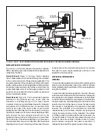
NON-ANTILOCK APPLICATION (FIGURE 3)

During normal non-antilock braking, both solenoids are de-
energized (no electrical power). Brake application air enters
the supply port of the modulator and flows to, and through,
the open exhaust solenoid then to the exhaust diaphragm.
Air pressure, along with spring force, seats the exhaust
diaphragm on the exhaust passage thus preventing the
escape of service air. Simultaneously, application air flows
to the supply diaphragm and forces it away from its seat. Air
flows past the open supply and out the modulator delivery
port to the service brake chambers.

Summary of Contents for M-21

Page 1: ...f individual wheel control applications the modulator is always the last control valve through which air passes on its way to the service brake actuator and a solenoid assembly which contains one norm...

Page 2: ...21 OR M 22 MODULATOR TO ANTILOCK CONTROLLER TO ANTILOCK CONTROLLER TO ANTILOCK CONTROLLER TO ANTILOCK CONTROLLER They are as follows Identification Air Line Connection 1 Supply incoming air from foot...

Page 3: ...SUPPLY DIAPHRAGM SUPPLY SOLENOID SPRING EXHAUST DIAPHRAGM EXHAUST SOLENOID BRAKE CHAMBER EXHAUST PORT FIGURE 4 M 21 M 22 MODULATOR NON ANTILOCK APPLICATION HELD POSITION BRAKE VALVE SPRING SUPPLY DIA...

Page 4: ...lifts the exhaust diaphragm from its seat Returning air flows past the open exhaust and out the modulator exhaust port Air will also flow past the open supply diaphragm and back to the application de...

Page 5: ...creased The modulator can enter the antilock hold or re apply mode from the antilock exhaust mode ANTILOCK HOLD The antilock controller will place the modulator in the hold position when it senses tha...

Page 6: ...ten or replace as necessary 4 Perform the ROUTINE OPERATION AND LEAKAGE TESTING described in this manual OPERATION LEAKAGE TESTS LEAKAGE TESTING 1 Park the vehicle on a level surface and block or choc...

Page 7: ...OURCE Read 3 5 to 5 OHMS B EXHAUST to SOURCE Read 3 5 to 5 OHMS C EXHAUST to HOLD Read 7 to 10 OHMS D Individually test the resistance of each pin to vehicle ground and note there is NO CONTINUITY If...

Page 8: ...ITION BRAKE VALVE SPRING SUPPLY DIAPHRAGM FIGURE 9 M 21 M 22 MODULATOR CONNECTOR VIEW M 21 MODULATOR M 22 MODULATOR CONNECTOR HOLD EXHAUST SOURCE EXHAUST HOLD SOURCE CONNECTOR SUPPLY SOLENOID SPRING E...

Page 9: ...rized air systems make certain to drain the air pressure from all reservoirs before beginning ANY work on the vehicle If the vehicle is equipped with an AD IS air dryer system or a dryer reservoir mod...

Page 10: ...10...

Page 11: ...11...

Page 12: ...12 BW1664 2004 Bendix Commercial Vehicle Systems LLC All rights reserved 6 2004 Printed in U S A...

Reviews: