background image

4

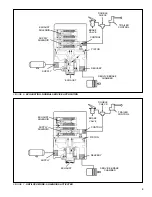
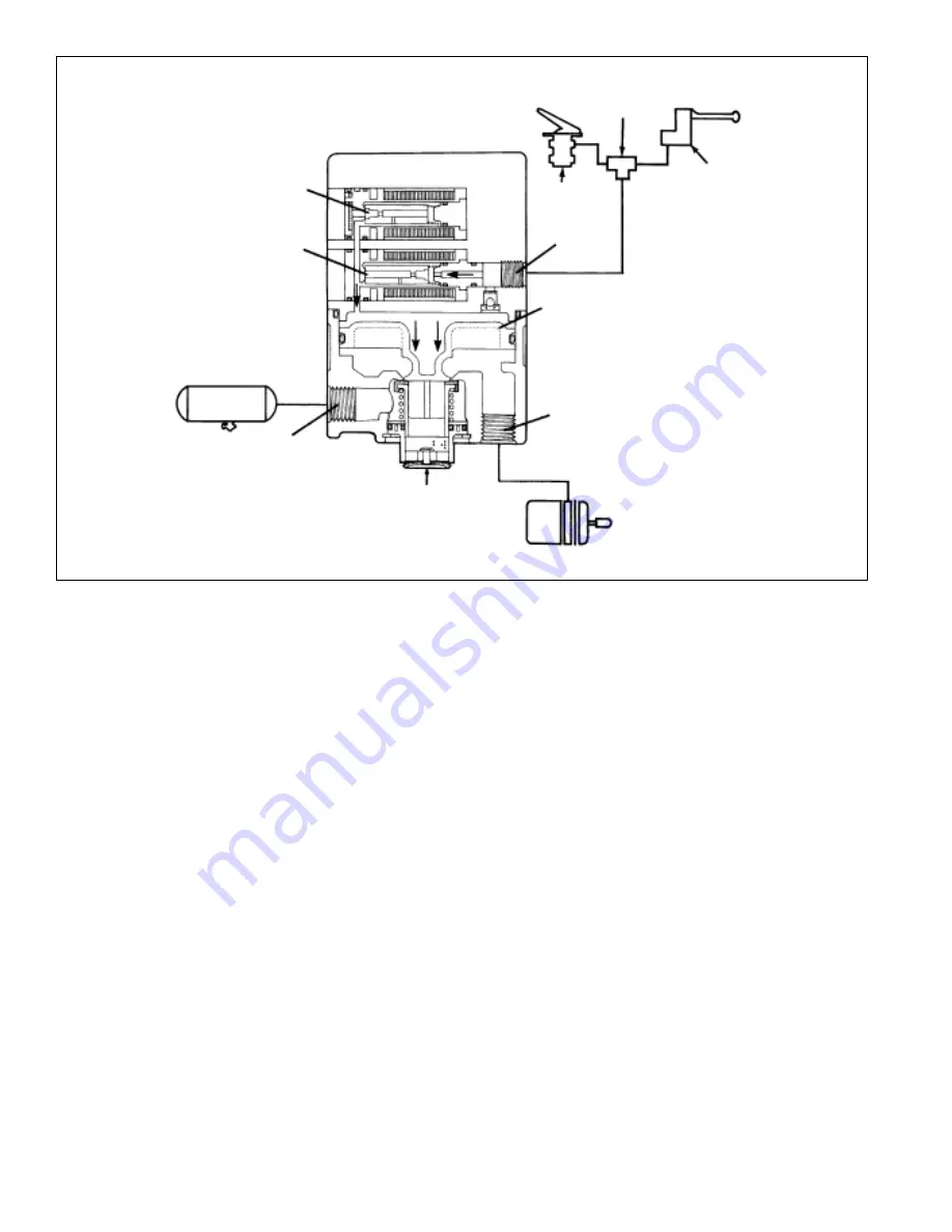
BALANCED POSITION: 

Normal Service Application

The modulator reaches a balanced position when control
pressure acting upon the top side of the piston approaches
that of the air acting upon the underside of the piston. The
piston moves upward and closes the inlet valve, while the
exhaust remains closed. This prevents the modulator from
delivering or exhausting air.

EXHAUSTING: 

Normal Service Application

When the brake valve is released, control pressure exhausts
through the supply solenoid and the check valve in the
solenoid housing and out the exhaust port of the brake valve.
As the piston moves upward, the modulator's exhaust opens,
allowing air from the piston's underside to exhaust through
the modulator exhaust port.

ANTILOCK MODE:

 Solenoids Activated

If a service brake application is made and the EC-12

controller senses wheel lockup, it will command the antilock
system to alter the service brake application.

When activated, shuttles within the solenoids alter the
application and exhaust of control air pressure. The supply
solenoid closes, preventing control line pressure from entering
the modulator. Then the exhaust solenoid opens, allowing
control pressure to exhaust from the top side of the piston
through the exhaust port of the solenoid assembly. This
activity occurs in a pulsating manner, simulating "pumping
of the brakes."

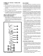
PREVENTIVE MAINTENANCE

1. Every 3 months; 25,000 miles; or 900 operating hours

perform SERVICE CHECKS.

2. Every twelve months; 100,000 miles; or 3600 operating

hours, disassemble the relay valve portion of the M-12
Modulator and clean parts with mineral spirits. DO NOT
DISASSEMBLE THE SOLENOID ASSEMBLY. Replace
all rubber parts and any parts worn or damaged. Check
for proper operation before placing vehicle in service.

FIGURE 5 - BALANCED POSITION: NORMAL SERVICE APPLICATION

TRAILER

CONTROL

DOUBLE

CHECK

BRAKE

VALVE

CONTROL

PISTON

DELIVERY

EXHAUST

SUPPLY

EXHAUST
SOLENOID

SUPPLY

SOLENOID

SERVICE BRAKE

CHAMBER

Summary of Contents for MC-12 MODULATOR CONTROLLER ASSY

Page 1: ...pin A and optionally pin B from the auxiliary terminal blue wire of the trailer s 7 pin connector DESCRIPTION The Bendix MC 12 modulator trailer antilock system is designed to improve vehicle stabilit...

Page 2: ...ht 14 16 14 16 14 16 10 11 N P Wheel Speed Sensor 16 18 16 18 16 18 12 13 M L Wheel Speed Sensor 16 18 16 18 16 18 Antilock Connector Pin B is an option and is used to provide constant power to the MC...

Page 3: ...s on and remains on when the trailer brakes are actuated a system problem has occurred The EC 12 controller contains a diagnostic window which FIGURE 3 SPEED SENSOR VOLTAGE CYCLE OUTPUT PEAK TO PEAK P...

Page 4: ...lock system to alter the service brake application When activated shuttles within the solenoids alter the application and exhaust of control air pressure The supply solenoidcloses preventingcontrollin...

Page 5: ...ACTIVATED EXHAUST SUPPLY EXHAUST SOLENOID CONTROL DOUBLE CHECK TRAILER CONTROL BRAKE VALVE DELIVERY PISTON SUPPLY SOLENOID SERVICE BRAKE CHAMBER DELIVERY PISTON EXHAUST SUPPLY EXHAUST SOLENOID CONTRO...

Page 6: ...injury resulting from contact with moving rotating leaking heated or electrically charged components 3 Do not attempt to install remove disassemble or assemble a component until you have read and tho...

Page 7: ...ve the EC 12 controller 1 from the M 12 modulator by removing the controller s four mounting bolts 2 Lift the controller off the M 12 modulator and detach the wire harness from the base of the control...

Page 8: ...controller onto the solenoid assembly and secure with the four 1 2 bolts and lock washers Torque to 30 60 in Ibs OPERATIONAL AND LEAKAGE TEST 1 Chock wheels Fully charge air brake system and adjust br...

Page 9: ...HE TRAILER WHILE PERFORMINGTHE INITIALSTART UPPROCEDURE and following the directions contained in the procedure Be sure to record a failure before resetting the system Reset by holding a magnet capabl...

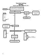
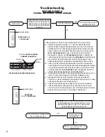
Page 10: ...DTO TRACTOR TURNIGNITIONON APPLY TRAILERSERVICEBRAKESAND OBSERVESTATUSLAMPMOUNTED ONTRAILER NO DID STATUS LAMP ILLUMINATE GO TO SECTION I STATUS LAMP TESTING ARE STOP LAMPS ILLUMINATED YES TEST FOR PO...

Page 11: ...RDER PRESENTED AND AFTER REPLACING OR TESTING EACH COMPONENT TEST THE STATUS LAMP OPERATION 1 CHANGE TRAILER STATUS LAMP BULB 2 CHECK TRAILER STATUS LAMP WIRING GROUND 3 CHECK CONTINUITY OF WARNING WI...

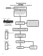
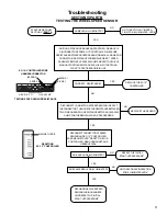
Page 12: ...NO ARE ANY RED LED s ILLUMINATED YES NO YES GOTOSECTIONIV TESTINGFORPOWER TOTHEEC 12 CONTROLLER NOTE AND RECORD THE CONDITION OF ALL RED LEDS GO TO SECTION III INSPECTION FOR ILLUMINATED LEDS RED LEDs...

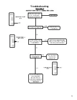
Page 13: ...S1 OR SNS2 LED ILLUMINATED IS RED MOD LED ILLUMINATED YES NO TESTING MOD LED IFANYOTHERREDLEDs AREILLUMINATED REPLACETHEEC 12 CONTROLLERANDREPEAT THE INITIALSTART UP PROCEDURE GO TO SECTION V TESTING...

Page 14: ...URE YES NO MAGNET HERE PERFORMAMAGNETICRESETBY PASSINGAMAGNETOVERTHE RESET INEC 12 CONTROLLER DIAGNOSTICWINDOWTHEN REMOVEMAGNET TURNIGNITIONOFF DONOTAPPLYBRAKES RECONNECTWIREHARNESSTOEC 12 CONTROLLER...

Page 15: ...RETURNED TOTHISSTEP TWICE REPLACETHE EC 12 CONTROLLER REPLACEEC 12 CONTROLLER NO GO TO SECTION III INSPECTION FOR ILLUMINATEDLEDS AND RETEST IFFAILUREPERSISTS REPLACETHEEC 12 CONTROLLER WHITE BLACK WH...

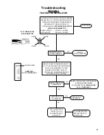
Page 16: ...N P RESISTANCE FORBENDIX WS 20 SPEEDSENSORSHOULDBEBETWEEN1500 2500 OHMS REFERTOVEHICLEMAINTENANCEMANUALIFOTHERTHANTHE WS 20 SPEEDSENSORISINUSE IFRESISTANCE NOTCORRECT DISCONNECTCONNECTORATSPEEDSENSOR...

Page 17: ...INSPEC TION FOR ILLUMINATED LED s SAME LED s ILLUMINATED NO YES RECONNECTCONNECTORATSPEED SENSORANDEC 12 CONTROLLER PASSMAGNETOVER RESET ONEC 12 CONTROLLER REMOVEMAGNETAND OBSERVELEDs IGNITIONOFFSERV...

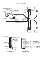
Page 18: ...PWR LED green EC 12 Controller Power TRAILER MOUNTED STATUS LAMP POWER FROM STOPLIGHTS GROUND 7PIN TRAILER ELECTRICAL CONNECTOR CONSTANT POWER FROM TRACTOR IGNITION OPTIONAL CONNECTION GROUND A B C D...

Page 19: ...19 NOTES REFERENCES...

Page 20: ...BW1667 2004 Bendix Commercial Vehicle Systems LLC All rights reserved 4 2004 Printed in U S A...

Reviews: