14
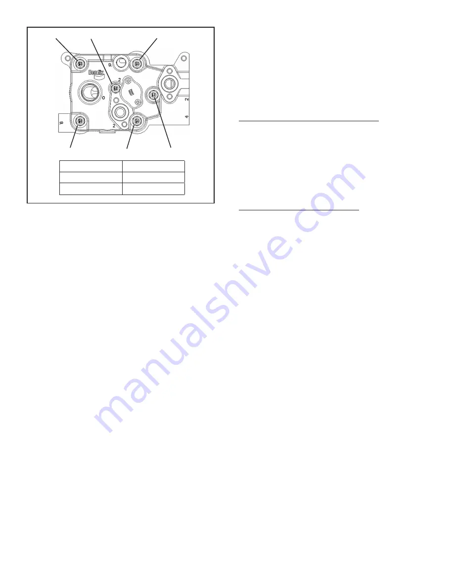
FIGURE 11 -
COMPRESSOR HEAD BOLT TORQUE
SEQUENCE
PART TWO: UNLOADER INSTALLATION
7. Apply a coating of the lubricant — provided in the
unloader kit — into the two unloader bores. Apply
additional lubricant to the three o-ring grooves on the
unloader piston (10). Install the three o-rings (7, 9, 11)
into the appropriate o-ring grooves on the unloader
piston. Note that the o-ring (7) installs inside the top
of the unloader piston. Apply another coating of the
lubricant onto the exposed o-ring surfaces and onto
the large diameter of the balance piston (6). Install
the unloader piston with the pre-installed o-rings into
the cylinder head unloader bore making certain not to
damage them in the process.
8. Install the balance piston spring (8) in the unloader
piston (10).
9. Apply a coating of lubricant to the largest diameter of
the balance piston (6). Install the small diameter end
of the balance piston through the center of the balance
piston spring (8).
10. Install the unloader cover gasket (5) on the cylinder
head (13) making certain both screw holes align.
11. Position the unloader cover (4) on top of the balance
piston (6) making certain the stamped logo on the
unloader cover (4) is visible.
12. Press and hold the unloader cover in place on the
cylinder head. Install both unloader cover cap screws
(2). Torque the unloader cover cap screws (2) to 62–71
in-lbs (7–8 N•m).
PART THREE: INLET & TOP COOLANT FITTING
INSTALLATION
If the inlet fitting (35) and/or the top coolant fitting (36)
where previously removed, they should now be installed;
otherwise skip step 13.
13. There are two options for the top coolant fitting (36).
Identify the fitting you have from the two options shown
in Figure 12a and follow the steps for installation.
Option 1: M16 x 1.5–6g (ISO 9974) fitting. Back off
lock nut as far as possible. Screw fitting into port until
the leading surface of the lock nut contacts the face of
the port. Light wrenching may be necessary. To align
the tube end to the position as defined in Figure 12,
unscrew the fitting by the required amount, but not more
than one full turn. Using two wrenches, hold fitting in
desired position and tighten locknut to 319–354 in-lbs
(36–39.5 N•m).
Option 2: M16 (tapered thread) fitting.
Note: It may be
necessary to apply Teflon tape to the threads of the
fitting to aid sealing of the threads
. Install the fitting into
the coolant port to “finger tight”. Then install 2 additional
turns plus turn to position.
Next, install the inlet fitting (35) into the inlet port of the
compressor. Back off the lock nut as far as possible.
Make sure the back-up washer is not loose and is
pushed up as far as possible. Screw fitting into port
until the back-up washer contacts the face of the port.
Light wrenching may be necessary. To align the tube
end to the position as defined in Figure 12, unscrew
the fitting by the required amount, but not more than
one full turn. Using two wrenches, hold fitting in desired
position and tighten locknut to 575–633 in-lbs (65–72
N•m).
PART FOUR: DISCHARGE JUMPER ASSEMBLY
INSTALLATION (REFER TO FIGURE 12)
14. Apply a coating of lubricant to the two discharge jumper
o-rings (40) and install the o-rings into the two o-ring
grooves on the cylinder head (13).
15. If the safety valve (12) was previously removed from
the discharge jumper (41), screw the safety valve into
the side port of the discharge jumper (37) and torque
to 200–249 in-lbs (22.5–28 N•m).
16. Position the discharge jumper (37) over the cylinder
head (13) such that it lines up with the four attachment
bolt holes.
Refer to Figure 13
to ensure proper
orientation on the cylinder head (13) Note: There is only
one way the discharge jumper can be installed on the
cylinder head.
17. Install the discharge jumper washer (39) and cap screw
(38) in each of the four holes on the discharge jumper
(37). Hand tighten the four cap screws and torque in a
cross pattern to 115–133 in-lbs (13–15 N•m).
2, 8
1, 7
5, 11
3, 9
6, 12
4, 10
Sequence
Torque (Nm)
1 through 6
20
7 through 12
31-34


