2
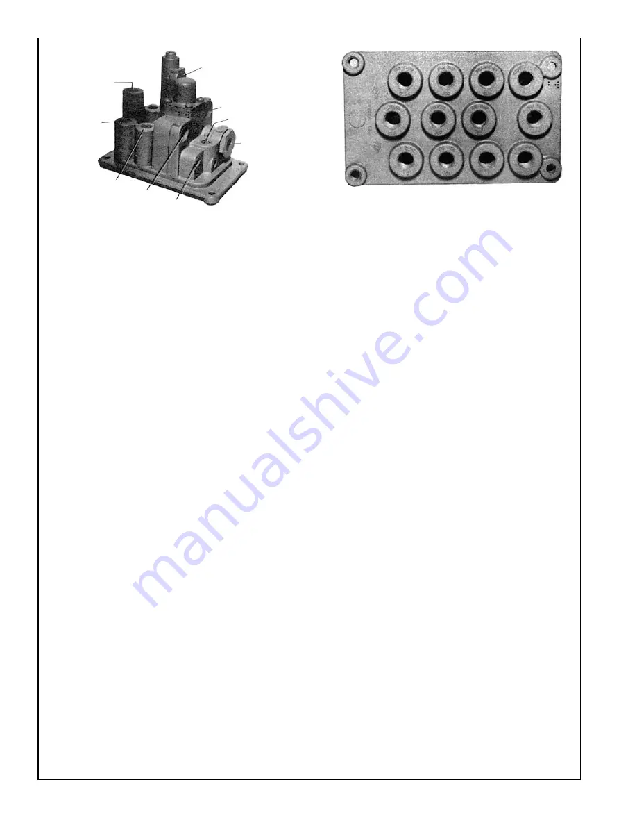
ENGINE SIDE
FIGURE 1
Port
Ident. on
No.
Casting
Function
1
Frt. Sup.
Supply from No. 2 circuit reservoir.
Blue
2
Park Sup.
Delivers air from double check valve
Red
area to spring brake relay valve (R-8).
3
Rear Sup.
Supply from No. 1 circuit reservoir.
Green
4
Rad. Fan
Delivers protected air supply from
Blk.
PR-4 valve. Suggested use - air
operated fan clutch.
5
Diff. Lock
Connects directly to port No. 9 (Fig.
Blk.
2) in cab. Suggested use - manifold
connection to differential lockout
mechanism. This is a 90
0
pass-through
passage.
6
Trl. Sup.
Connects directly to port No. 10 in
Yel.
cab. Suggested use - deliver air from
trailer supply valve (such as BW PP-7)
to trailer. This is a 90° pass-through
passage.
7
(None)
Connects directly to port No. 11 in
cab. Suggested use - any auxiliary
manifold function. This is a straight
through passage.
8
Air Rest.
Connects directly to port No. 12 in
Blk.
cab. Suggested use - air cleaner
restriction gauge. This is a straight
through passage.
9
Prk. Del.
Connects directly to port No. 8 (Fig.
Red
2) in cab. Suggested use - deliver air
from park control valve to spring
brake control valve (SR-1
™
valve).
This is a straight-through passage.
10
Spg. Brk.
Connects to secondary circuit reservoir
Rest. - Grn. and to port No. 4 (Fig. 2) in cab.
Suggested use - supplies secondary
reservoir air to the balance port of the
SR-1 spring brake control valve.
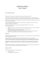
Port
Ident. on
No.
Casting
Function
1
Frt. Gauge
Connects to gauge for No. 2 circuit
Blue
reservoir.
2
Prk. Sup.
Supplies air from double check valve
Red
to park control valve.
3
Rear Gauge Connects to gauge for No. 1 circuit
Green
reservoir.
4
Hand Brake Supplies air from No. 2 circuit reservoir
Supply
to trailer hand control valve in
Green
cab. Connects with No. 10 on engine
side.
5
Access
Supplies protected air from PR-4
™
valve
Blk.
to any accessory control in cab.
6
Access
Supplies protected air from PR-4
™
valve
Blk.
to any accessory control in cab.
7
Trl. Sup.
Supplies air from double check valve
Red
to trailer supply valve (tractor
protection).
8
Prk. Del.
Receives air from delivery of park
Red
control valve to deliver to SR-1
™
spring
brake control valve. Connects with No.
9 on engine side.
9
Diff. Lock
Receives air from delivery of differen-
tial lockout control valve. Connects
with No. 5 on engine side.
10
Trl. Del.
Receives air from trailer supply valve
(tractor protection) to supply trailer.
Connects to No. 6 on engine side.
11
(None)
Auxiliary manifold for any accessory
function connects to No. 7 on engine
side.
12
Air Rest.
Suggested use - air cleaner restriction
Blk.
gauge. Connects with No. 8 on engine
side.
NO.1
NO.4
NO.2
NO.3
NO.9
NO.8
NO.7
NO.6
NO.5
1
2
3
4
5
6
7
8
9
10
11
12
CAB BULKHEAD SIDE
FIGURE 2


