background image


AeroNav 900/880 Series Pilot’s Guide 

89000039-010 
Rev 1 May 2019 

Aux Subsystem

 5-27 


Datablock Item Title 

and Image 

Content 

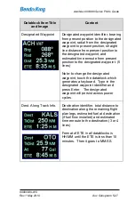
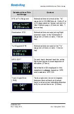
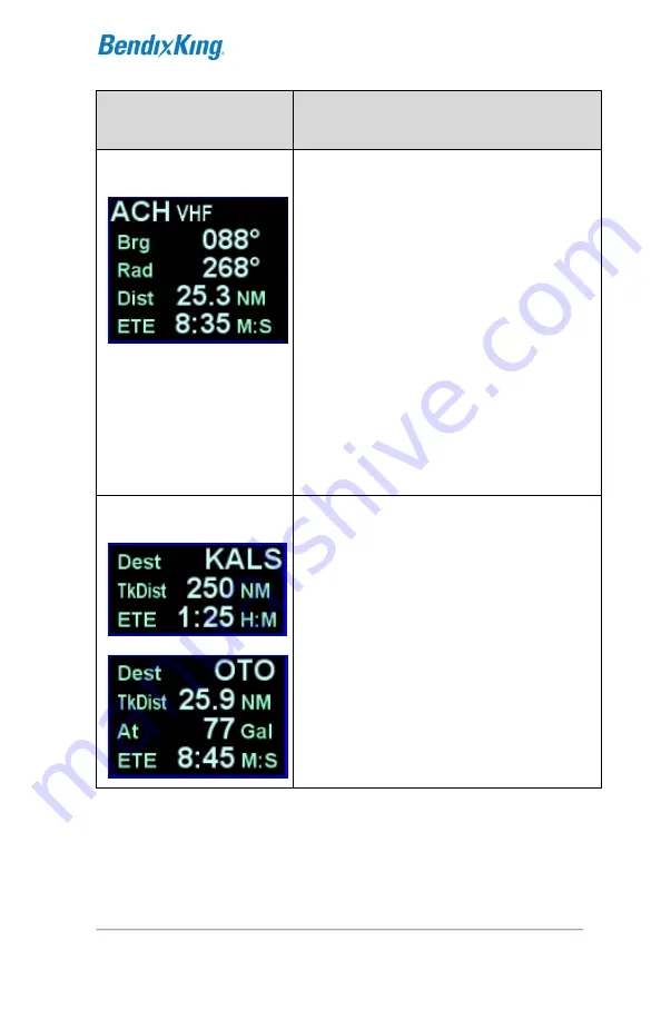
Designated Waypoint 


Designated waypoint identifier, bearing 
from present position to the designated 
waypoint, radial from the designated 
waypoint to present position, straight 
line distance from present position to 
the designated waypoint, and 
estimated time enroute from present 
position to the designated waypoint. (5 
lines) 
 
Note: to change the designated 
waypoint, touch the datablock which 
generates a keyboard.  Type in the 
designated waypoint identifier and 
press Enter.   The designated 
waypoint will persist across power 
cycles. 

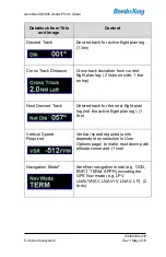
Dest. Along Track Info. 


Destination identifier, total distance to 
destination along the remaining flight 
plan legs, estimated fuel at destination 
(if fuel flow installed) and estimated 
time enroute to the destination.(3 or 4 
lines) 
 
Format of ETE in all datablocks is 
HH:MM until the ETE is less than 10 
minutes.  Then it goes to MM:SS. 

Summary of Contents for AeroNav 880

Page 1: ...AeroNav 910 SVS FMS GPS NAV COM AeroNav 900 FMS GPS NAV COM AeroNav 905 SVS FMS GPS AeroNav 880 FMS GPS Pilot s Guide...

Page 2: ...505 903 6148 www bendixking com Email techsupport bendixking com www avidyne com support license asp BendixKing Part Number 89000039 010 Printed in the U S A May 2019 This document contains technical...

Page 3: ...Rev 1 May 2019 i Record of Revision REVISION REVISION DATE DESCRIPTION 0 03MAY2019 Initial Release 1 14MAY2019 Updated revision number Deleted Materials License Agreement and copyright information Add...

Page 4: ...AeroNav 900 880 Series Pilot s Guide 89000039 010 ii Rev 1 May 2019 Blank Page...

Page 5: ...16 Brightness Controls 1 17 Start Up Sequence 1 18 Database Currency States 1 21 Page Layout and Formats 1 23 Com Nav 1 25 Frequency List 1 33 Transponder Control and Display 1 35 Direct To Operations...

Page 6: ...ttern 3 18 Circular Orbits 3 20 Deleting A Holding Pattern 3 23 Editing A Holding Pattern 3 24 Activating a Flight Plan 3 24 Flight Plan Sequencing 3 24 Lateral Offsets 3 25 Flight Plan Discontinuitie...

Page 7: ...or Map Overlay 4 28 Terrain 4 30 TERRAIN AWARENESS TA 4 31 Forward Looking Terrain Alerting FLTA 4 33 500 Callout 4 36 TERRAIN ALERTING WARNING SYSTEM TAWS 4 37 Premature Descent Alert PDA 4 39 Excess...

Page 8: ...1 NAV SOURCE KNOB BUTTON 6 5 OBS MODE 6 9 VOR COURSE DEPICTION 6 13 ARMED VS ENGAGED ACTIVE INDICATIONS 6 14 FMS HOOKS 6 15 COURSE CHANGES AND HOLDS 6 18 AUTO VLOC TUNING 6 19 TRANSITION ALTITUDES LEV...

Page 9: ...LOVES 7 39 CHARGING FROM THE USB 7 41 INTEGRATION WITH THE IFD100 MOBILE APP 7 42 DEMO MODE 7 43 DATA TRANSFER TO FROM EXTERNAL DEVICES 7 46 REGULATORY COMPLIANCE STATEMENTS 7 50 Radio Regulatory Comp...

Page 10: ...uide 89000039 010 6 Table of Contents Rev 1 May 2019 Configuring as a client with a static IP 7 77 PAIRING A BLUETOOTH KEYBOARD 7 79 Verification of successful pairing 7 84 CLEANING THE DISPLAY 7 87 S...

Page 11: ...areas marked as NOTE within this manual identify certain situations or areas of operation having heightened safety implications While it is important for the operator to be familiar with all of the in...

Page 12: ...radio whose primary function is to conduct nav com transponder tuning and communication and serve as the principal navigation sensor system for all IFR VHF VLOC and GPS based navigation and instrumen...

Page 13: ...stalled in the required field of view The AeroNav 880 cannot be used to execute terminal area procedures that rely on radio navigation The AeroNav 880 bezel differs physically from the AeroNav 900 in...

Page 14: ...using a symbol AERONAV 910 The BendixKing AeroNav 910 is a GPS Nav Com radio whose primary function is to conduct nav com transponder tuning and communication and serve as the principal navigation se...

Page 15: ...or additional aircraft state awareness In degraded conditions the synthetic vision view will be replaced with a traditional blue over brown attitude indication The attitude sensing and depiction of th...

Page 16: ...the left side of the bezel are absent the nav source selection knob is replaced by an OBS button and the volume knob is replaced by a single function on off button Supplemental AeroNav 905 functions i...

Page 17: ...System Overview 1 7 DOCUMENTATION CONVENTION Throughout this document capabilities that are not applicable to the AeroNav 905 are identified using a symbol Also capabilities that are applicable only...

Page 18: ...g synthetic vision view Terrain Awareness Forward Looking Terrain Alerting FLTA Terrain Alerting Warning System TAWS optional Weather Datalink ADS B position and display Lightning sensor depictions We...

Page 19: ...r range changing on maps and charts is fully enabled The system has been designed for single pilot IFR operation and features a Page and Tab user interface Most functions revolve around the Page Funct...

Page 20: ...available tabs by pressing the left or right side of the Page Function Key Continual pressing of one side of the function key will automatically step through the tabs Page Function Keys and Tabs AeroN...

Page 21: ...ypes RIGHT KNOB LABELING The bottom right AeroNav knob is context sensitive Displayed in the lower right corner of the display the knob label indicates the function of the knobs and the knob button on...

Page 22: ...oNav Feature Function Color Page Function Keys Green Active White Available but not currently active Note AUX can also be Red Yellow or Cyan if there is an active alert as described later in this manu...

Page 23: ...s As a retrofit installation the AeroNav 900 and AeroNav 910 were designed to be slide in replacements for a Garmin 530 W unit Similarly the AeroNav 880 and AeroNav 905 were designed to be slide in re...

Page 24: ...s one extra Page Function Key labeled SVS to the left of the FMS key Starting in the top left corner and working counter clockwise around the bezel the AeroNav has Power Volume Squelch knob Frequency...

Page 25: ...pendent Six 6 Dedicated Function Keys consisting of o Direct To D o Procedure PROC o Nearest NRST o Frequency List FREQ o Enter ENTR o Clear CLR Ambient Light Sensor CDI Nav Source knob Power button G...

Page 26: ...the AeroNav display will show an BendixKing logo It will take several seconds for the AeroNav to complete the power up process The power button can be used to turn the unit off and to turn the unit ba...

Page 27: ...c control of brightness in response to the ambient light sensor that is embedded in the bezel The user accessible controls for all are on the AUX page using the User Options LSK of the Setup tab Brigh...

Page 28: ...med on this page and it will automatically be removed after several seconds A software version and database currency page is displayed only if there any expired databases BendixKing does not recommend...

Page 29: ...n initial fuel That should resolve itself within a few seconds Another example concerns the FMS nav database initialization where the message Loading nav database may be displayed on any of the FMS ta...

Page 30: ...TECHNIQUES Bluetooth Networking Initialization Period The Bluetooth and networking interfaces may experience a 1 2 minute delay during post start initialization before becoming functional The icons i...

Page 31: ...ar Yellow Charts Issue Date Between 14 and 21 Days Old i e up to a week out of date Update Available Next Cycle Date Light Green Charts Issue Date Older Than 21 Days i e more than a week out of date U...

Page 32: ...22 System Overview Rev 1 May 2019 TIPS AND TECHNIQUES Manual Check of Database Dates Even if the databases are all current you can still view the date status of each database from the AUX page Databas...

Page 33: ...es to be shown are configurable For the AeroNav 880 and AeroNav 905 that area can be configured to show other datablocks just like those on the right side of the page Page Layout AeroNav 900 Shown Use...

Page 34: ...pages can display datablocks along the right edge of the display The FPL tab and NRST tab on the FMS page and the Map tab on the MAP page are prime examples In the cases where this is available a labe...

Page 35: ...quency is displayed in green and a standby is displayed in white The number of available standby frequencies is configurable Display of the frequencies can be formatted in several ways via the User Op...

Page 36: ...e handy in local area operations when just a few standard frequencies are expected to be used for a flight for example ATIS Ground and Tower frequencies can be entered in three com slots for quick swa...

Page 37: ...hich serves as a usable means to Tune Identify Monitor If a slot is receiving a voice transmission a RX indication will be displayed along the right edge of the given com slot When the active frequenc...

Page 38: ...ol of com radios nav radios and a remote transponder if equipped To switch between controls push the lower left knob Subsequent tuning operations will be performed on the displayed transceivers Follow...

Page 39: ...ter the desired frequency into the numeric keypad and press ENTR either on the virtual keypad or on the bezel The virtual keyboard will be dismissed after ten seconds of inactivity The nav radio may b...

Page 40: ...ration of the frequency list The 1 Standby can also be tuned from other pages on the AeroNav such as the INFO or NRST Tab on the FMS page Invalid Frequency Entry Attempt Attempting to type an invalid...

Page 41: ...f continuous transmission a Stuck Mic CAS message Blue Advisory message will be displayed and the transmitter will be disabled until the stuck mic condition is resolved Remote Tuning Control and Frequ...

Page 42: ...e com frequency function is installed as a dedicated button on the yoke allowing frequency swapping without removing hands from the controls Other remote tuning and frequency swapping capability is pr...

Page 43: ...Delivery associated with either the origin airport or destination airport when airborne and more than 5nm from the origin airport Enroute frequencies associated with airports ARTCC and FSS within 40nm...

Page 44: ...tab can be scrolled by swiping up or down on the touchscreen or by rotating the right inner knob To move the cursor to the desired frequency rotate the right inner knob or touch the frequency To tune...

Page 45: ...t and top sides of the display A round R reply indication will light up in the transponder datablock area whenever the transponder is in an active Reply state If the AeroNav is unable to communicate w...

Page 46: ...to be dismissed and the original code will be restored Transponder code can also be entered using the lower left knob First press the knob until the transponder tuning data is displayed in the upper l...

Page 47: ...in air and GND SBY when on ground When airborne the transponder should always be set to ALT unless otherwise directed by Air Traffic Control VFR To quickly set the regional VFR code press the VFR key...

Page 48: ...the desired waypoint press the ENTR function key along the right edge of the bezel twice Direct To Enter Enter or touch the Activate dialog box that pops up on the display to accept If a different wa...

Page 49: ...n the desired waypoint is displayed press Enter on the keypad or bezel to accept Twist the inner ring of the lower right AeroNav knob while the pop up green Direct To dialog box is displayed to go int...

Page 50: ...e NRST function key changes the nearest list to another category as defined in the list below o Nearest Airports o Nearest Airports to Destination o Nearest VORs o Nearest NDBs o Nearest Intersections...

Page 51: ...op down box appears over the intended data field twist the bottom right AeroNav knob to scroll up or down the list until the desired procedure is highlighted and then push the knob in to add that proc...

Page 52: ...ps most importantly hybrid touch is useful during turbulent or bumpy flight conditions where it is often very difficult to precisely and reliably touch the desired point on the display Having a physic...

Page 53: ...Planning Rubber banding Changing the Primary Nav Source Calling up a map page info box Starting the Frequency List Selecting a 2 or 3 standby frequency for swapping into the active frequency slot Freq...

Page 54: ...Alpha Keyboard Virtual Numeric Keyboard Each keyboard has a scratchpad in the lower right corner The scratchpad is a free text field for data entry with some data entry validity logic applied to the d...

Page 55: ...roNav installations Invalid Keyboard Entry Alert TIPS AND TECHNIQUES Optimal Touch Performance To maximize touch performance the more surface area of a finger that can make contact with the glass the...

Page 56: ...eyboard can be used instead COOL FEATURE Convenient Data Entry If air is turbulent or touch is turned off or physical access to the controls is difficult an external keyboard can be an easier way to e...

Page 57: ...hting for the keyboard The vertical two headed arrow key is primary 1 standby swap The BendixKing logo key is a space bar The up down arrow keys can be used for page navigation in the same way the inn...

Page 58: ...SETUP tab on the AUX page the second AeroNav will automatically present a virtual keyboard when the other AeroNav is in a mode where data is being entered or edited In other words if Keyboard Conveni...

Page 59: ...nfiguration either both are WAAS or both are non WAAS If one AeroNav is set up with a WAAS antenna and one is set up with a non WAAS antenna then the FMS related data flight plans waypoints routes wil...

Page 60: ...es must be satisfied CrossSync must be turned on in both AeroNavs this is a maintenance mode setting Both AeroNavs must have the same SBAS antenna configuration Both AeroNavs must have the same nav da...

Page 61: ...E Data Sharing Tolerates Inconsistent Databases While BendixKing strongly recommends the databases on each AeroNav be kept up to date and on the same cycle data sharing between AeroNavs as defined abo...

Page 62: ...treaming from AeroNav to third party application to allow automatic approach chart selection and display on the third party application Traffic data streaming from AeroNav to third party application f...

Page 63: ...he user selects Ignore or disables the Network or BT via the options page the gray logos above are depicted with a slash through them indicating they are not connected due to being actively disabled b...

Page 64: ...eft corner of the AeroNav can be used to sever the WiFi and Bluetooth link to the panel AeroNav Press and hold the power knob button down until the countdown box on the display appears and then let go...

Page 65: ...choices in the FMS and WAAS glideslopes will be displayed when appropriate When configured to be connected to a non WAAS antenna or a non approved WAAS antenna at installation the AeroNav will not pro...

Page 66: ...the GNS system TIPS AND TECHNIEQUES Dual AeroNav Installations Should Only Use One WiFi For reliable WiFi operations BendixKing recommends turning off WiFi Network from the User Options page on one o...

Page 67: ...to check User Options and datablock selections to ensure set up for your personal preferences BendixKing recommends creating and using the Checklist utility and including a Before Takeoff checklist th...

Page 68: ...AeroNav 900 880 Series Pilot s Guide 89000039 010 1 58 System Overview Rev 1 May 2019 Blank Page...

Page 69: ...l Velocity Vector TVV Flight Path Marker FPM Airport flags Runway depictions 3D terrain 3D traffic 3D obstacles Large bodies of water oceans lakes major rivers The SVS page can also show attitude indi...

Page 70: ...e aircraft is pointing Synthetic Vision Page The SynVis field of view adjustment can be made by either pinch zoom gestures on the touchscreen display or by twisting either ring of the bottom right bez...

Page 71: ...ency The SynVis LSK L2 is the toggle between the synthetic vision image On and a traditional blue brown Attitude Indicator AI Off with a third state to turn the flight plan overlay on off There are no...

Page 72: ...depicted at the relative altitude and bearing as received from the traffic sensor consistent with the SynVis field of view As traffic draws nearer to your ownship position it grows in size in the Syn...

Page 73: ...which time the flag is removed and the runway outlines should be clearly visible If the AeroNav receives a valid METAR the airfield flag will be color coded to represent the ceiling and visibility co...

Page 74: ...des a means to turn on off cardinal heading tick marks and labels e g N NE E SE etc along the horizon line in the SynVis scene Heading Horizon Tick Marks and Labels The User Options page also provides...

Page 75: ...ed to show datablocks the datablocks overlay the terrain and the SynVis view is re centered in the available space To show the datablocks touch the Data tab on the right side of the display Holding th...

Page 76: ...l be depicted in the SynVis scene out to 12nm Standard high low and grouping symbology is used to depict obstacles Any obstacle in the database within a 5nm radius of the aircraft position and whose t...

Page 77: ...tween 100 below aircraft altitude and 1000 below aircraft altitude will generate a yellow threat bubble over the obstacle on the SynVis scene and the map pages Obstacles inside a 1 5nm radius of the a...

Page 78: ...AeroNav 900 880 Series Pilot s Guide 89000039 010 2 10 SVS Subsystem Rev 1 May 2019 Yellow Obstacle Threat Bubble Red Obstacle Threat Bubble...

Page 79: ...up page selections If obstacle filtering is disabled on the Map Setup page then all obstacles within 12nm will be displayed in the SynVis scene If obstacle filtering is enabled then the system will di...

Page 80: ...d 1000 below aircraft altitude will generate yellow hatched indications on the SynVis scene and the map pages Any terrain that is within a 10nm radius of the aircraft position and is 100 below aircraf...

Page 81: ...ll have 60 seconds of notice for a caution and 30 seconds for a warning Reduced terrain or obstacle clearance occurs when the TVV FPM is not projected to impact the terrain but the projected clearance...

Page 82: ...The difference between FLTA warnings and cautions is exclusively based on distance to go to projected impact points or reduced clearance areas The reduced terrain and obstacle clearance distance varie...

Page 83: ...yed and the arrowhead pointers indicate the direction and distance from desired glide path and glide slope In the example below the aircraft is virtually right on glide path but is displaced above the...

Page 84: ...f leaving the field of view at the upper or lower ends of scales for long due to potential visual cue confusion e g things may be much closer or further than they appear If the AeroNav is configured t...

Page 85: ...ev 1 May 2019 SVS Subsystem 2 17 The active runway in the FMS flight plan is highlighted with a magenta outline drawing the airfield identifier flag is planted at the runway threshold if known or airp...

Page 86: ...e L4 LSK will toggle to Retry Approach when on the published missed Retry Approach Option While On Missed Approach Deviations are indicated by both the SynVis scene depiction and the horizontal and ve...

Page 87: ...AeroNav 900 880 Series Pilot s Guide 89000039 010 Rev 1 May 2019 SVS Subsystem 2 19 above glideslope A pegged deviation indicator is displayed in yellow Deviation Indicators...

Page 88: ...VS Subsystem Rev 1 May 2019 Many published missed approaches contain a hold pattern The AeroNav FMS will enter the hold as published and remain in the hold indefinitely until commanded to exit the hol...

Page 89: ...av 900 880 Series Pilot s Guide 89000039 010 Rev 1 May 2019 SVS Subsystem 2 21 Once the Exit Hold LSK has been selected the AeroNav FMS will exit the hold at the published fix Exit Hold Has Been Comma...

Page 90: ...s no valid heading input to the AeroNav the TVV FPM is removed from the SynVis scene and the directional indication is labeled TRK indicating GPS track as the source SynVis with no Heading Input If th...

Page 91: ...unusual attitude recoveries High low pitch chevrons are also displayed in those extreme pitch flight path angle situations and point toward the horizon as well The following SynVis related failure co...

Page 92: ...eding the operational limits of the ARS below may result in a temporary loss of attitude display Body Pitch Roll rates up to 105 sec Body Yaw rates up to 70 sec Acceleration up to 4 5Gs Static and dyn...

Page 93: ...Depiction Unavailable In GPS Alignment SynVis depictions will not be available until the GPS has reached SBAS state SBAS WAAS configurations or FDE state non SBAS WAAS configurations NOTE Flight Plan...

Page 94: ...AeroNav 900 880 Series Pilot s Guide 89000039 010 2 26 SVS Subsystem Rev 1 May 2019 Blank Page...

Page 95: ...in the flight plan The INFO tab provides a method for showing information about aviation facilities contained in the navigation database The ROUTE tab provides a method for managing stored routes Sto...

Page 96: ...ht plan as created All deviation data most data block data and the times to go and fuel calculations are all based on that assumption Each leg of a flight plan has its own color coded background desig...

Page 97: ...xt sensitive knob located at the bottom right side of the AeroNav Rotation of the outer knob will move the cursor through the flight plan between insert and edit cursors for each row Think of this as...

Page 98: ...entered using the inner and outer knobs Initiating the operation by touching will put the field into edit mode and cause a virtual keyboard to appear allowing direct entry of a value If an operation...

Page 99: ...location e g user waypoint navaid airport In almost every case your hand can stay on the bottom right AeroNav knob Through a combination of pushes and turns you can enter the entire flight plan very...

Page 100: ...can be displayed using a mini format where legs are presented in a single row allowing more legs to be visible on the display The mini format is selected on or off using the FMS Setup page on the AUX...

Page 101: ...ially part of the flight plan to aid in situational awareness The preview feature is available whether modifications are being made on the ground or airborne While a preview is being displayed an temp...

Page 102: ...A procedure that contains the active leg is always shown using expanded view COOL FEATURE FMS Cursor Centered View One of the Map views available for use on the Map FPL tab of the FMS page is FMS Curs...

Page 103: ...on Departures Dropdown TIPS AND TECHNIQUES Vector Standard Instrument Departure SID Vector or Radar SIDs are not likely to be part of the list of available departures in the FMS dropdown This is due t...

Page 104: ...transitions first If the departure has more than one published enroute transition the FMS will present a dropdown showing those transitions and a transition must be selected If the departure has only...

Page 105: ...fferently based on whether the airport has a selected runway If the airport has a selected runway and that runway is applicable to the selected departure then the FMS will choose the runway transition...

Page 106: ...the FMS will select the first runway numerically that is applicable INSERTING A WAYPOINT To insert a waypoint into the flight plan rotate the right outer knob until an insert cursor is positioned whe...

Page 107: ...l keyboard but the LSK is obscured on the screen by the keyboard TIPS AND TECHNIQUES Back to Back Duplicate Waypoints Restriction The FMS will not permit entering back to back duplicate waypoints A du...

Page 108: ...tions available after that leg Scroll the cursor down through the list until the desired airway name is selected Note that airways are always at the bottom of the list Once the desired airway is selec...

Page 109: ...ide of the bezel to delete the waypoint Continue pressing the CLR button and it will walk up the flight plan deleting earlier waypoints as you go Waypoints can also be deleted by touching the waypoint...

Page 110: ...raint e g cross the waypoint at or above a specific altitude be at a specific altitude a specified distance prior to the waypoint etc This is accomplished by ensuring an edit cursor surrounds the wayp...

Page 111: ...then adjust the FMS OBS course using the external course adjust knob i e course set knob on a CDI or HSI or EFIS If there is no installed external course setting device then twist the AeroNav nav sou...

Page 112: ...the CDI HSI EFIS etc to set the desired inbound or outbound radial as required DELETING A FLIGHT PLAN Select the Routes tab of the FMS page Use the bottom right AeroNav knob to scroll to the desired f...

Page 113: ...MS will use a standard hold pattern when there is no defined published hold For those fixes that have multiple published holds associated with them a dropdown menu will be presented showing the variou...

Page 114: ...t s Guide 89000039 010 3 20 FMS Subsystem Rev 1 May 2019 CIRCULAR ORBITS If the optional Search and Rescue SAR Special Use Mission package is active then circular orbits can be added to the plan Circu...

Page 115: ...em 3 21 The function is activated on the FMS Setup page by setting the Patterns field to On Circular Orbit Pattern Selection in FMS Setup Once on the leg type is selected just like all other leg types...

Page 116: ...AeroNav 900 880 Series Pilot s Guide 89000039 010 3 22 FMS Subsystem Rev 1 May 2019 Select the Orbit waypoint option in the standard FMS insert cursor drop down list Circular Orbit Dropdown Selection...

Page 117: ...the orbit on the extended radial between the orbit fix and the aircraft Just like a traditional holding pattern there is no insert cursor between a fix and a subsequent orbit The only way to get out o...

Page 118: ...aphical representation as illustrated below Procedure Turn Leg ACTIVATING A FLIGHT PLAN When a flight plan is entered on the ground the flight plan will be inactive and no guidance will be provided To...

Page 119: ...to the primary nav frequency It may desirable to turn off this feature on one of the AeroNavs in a dual installation to allow depiction of a crossing radial for reference before crossing a VOR Also wh...

Page 120: ...hen there is a discontinuity between legs A discontinuity occurs when the FMS cannot compute the guidance to the next leg due to an invalid leg type combination based on preset guidance rules The obje...

Page 121: ...the procedure including all altitude constraints into the FMS Take advantage of the system to stay ahead of the airplane by using the wind vector datablock selection a constant calculation of estimat...

Page 122: ...int of an approach past the Final Approach Fix FAF or in holds or procedures turns The FMS uses a default of 500 feet per minute descent rate or as edited in the Preferred Descent Rate field on the FM...

Page 123: ...rawn on the map that depicts the geographic point where at the current vertical speed the aircraft will reach the altitude target The altitude target is any crossing restriction on a waypoint that is...

Page 124: ...ow the Final Approach Fix FAF published altitude If your flight plan contains consecutive approaches and you activate the next approach during climb out from the previous approach and prior to reachin...

Page 125: ...clarity After pressing the knob the FMS will present a dropdown from which to select the desired procedure The process for using the dropdowns to select the arrival and or approach and any enroute an...

Page 126: ...re including related transitions the legs will be inserted into the flight plan and the corresponding destination airport field will contain the name of the procedure that was just inserted In expande...

Page 127: ...PROC key will step through all following destination airfields approaches and arrivals in the flight plan and wrap back around to the top of the flight plan When the dropdown is presented for the inte...

Page 128: ...g L2 LSK Activating a Leg TIPS AND TECHNIQUES Deleting an Approach From Active Flight Plan One of two techniques is recommended to delete a an approach from an active flight plan if you want to replac...

Page 129: ...light and scenarios the split page is especially helpful during arrivals This can be most useful to instantly correlate your flight plan with the graphical depiction on the map This aids in error redu...

Page 130: ...er a flight plan leg blue airfield legs has at least one published approach associated with it a chart icon is presented on the right edge of the flight plan leg By using the right hand knob on the Ae...

Page 131: ...nstalled in the airplane and providing METAR data to the AeroNav color METAR flags will be included in the flight plan leg depiction along the right edge This is designed to give you a quick weather r...

Page 132: ...and present a virtual keyboard or touch the field to present a virtual keyboard There is also a Paste LSK along the left edge of the AeroNav that will nominate the currently active leg of the flight p...

Page 133: ...uch nominates it into the 1 standby or by using the bottom right AeroNav knob to highlight the desired frequency and then push the knob to nominate it into the 1 standby slot Runways identifies the kn...

Page 134: ...he airport including any identifier and nav frequency and when an individual row has been selected via touch or the bottom right AeroNav knob it can further expand to provide a thumbnail map depiction...

Page 135: ...AeroNav 900 880 Series Pilot s Guide 89000039 010 Rev 1 May 2019 FMS Subsystem 3 41 Weather Data on Info Tab Info Tab Nearby Navaids...

Page 136: ...ute is represented by a single row with the route name on the left and the from and to points identified on the right side of the row Additionally there are two special purpose rows shown at the top o...

Page 137: ...without entering a name rotate the right outer knob to show the familiar insert cursor Use the same methods as described on the FPL page to edit the stored route When editing is complete press the Bac...

Page 138: ...e is loaded Starting with Release 10 2 0 0 the system will save manually entered altitude constraints but only for direct legs If you ve manually entered or changed an altitude constraint on a leg wit...

Page 139: ...te e g setting up multiple arrival scenarios when still far from destination can be accomplished by copying the active route on the Route tab renaming it for clarity and editing as desired When ready...

Page 140: ...ute will be presented for editing It is possible to invert the active flight plan by highlighting the Current Route row and pressing the Invert LSK Pressing the Back To Route List LSK with no changes...

Page 141: ...tab by either touching the row or using the bottom right AeroNav knob Once the desired route to be activated is highlighted press the Activate Route LSK along the left edge of the display The AeroNav...

Page 142: ...ther touching the dialog box or pressing the ENTR function key along the right edge of the display Deleting a Route COOL FEATURE The flight plan can be deleted by moving the cursor to surround the Cur...

Page 143: ...to create a waypoint with your current position No further action is required Enter Lat Lon Press the New LSK then press the Format LSK until the Lat Lon option appears and enter in your desired coor...

Page 144: ...point data is received from the external EFIS the AeroNav will automatically switch to the WPT tab if not already there NAMING A USER WAYPOINT Each user waypoint can be assigned a 5 character identifi...

Page 145: ...ESIGNATING A USER WAYPOINT AS AN AIRFIELD To designate a user waypoint as an airfield the waypoint must be manually named using the format AIRPORT XXXXXFT where XXXX is the field s elevation and note...

Page 146: ...ries Pilot s Guide 89000039 010 3 52 FMS Subsystem Rev 1 May 2019 When used in a flight plan the user defined airport will display as an airfield with no known runway orientation User Waypoint Airfiel...

Page 147: ...een the two formats is accomplished by opening or closing the side tab when on the Nearest page Full Nearest Tab The Nearest LSK along the left edge can be used to cycle through the various nearest ty...

Page 148: ...ose rows that contain a lower case blue info i symbol in the middle of the row touching the info i or using the bottom right AeroNav knob to highlight it and then pushing the knob will jump the page t...

Page 149: ...ype may have been For example if the Nearest VORs selection was the most recent display of nearest data and then the pilot selects a map page for more than 60 seconds when the Nearest tab is next sele...

Page 150: ...ries Pilot s Guide 89000039 010 3 56 FMS Subsystem Rev 1 May 2019 NOTE Nearest Lists Capped at 100nm Most Nearest lists will only display entries that are within 100nm of the current aircraft position...

Page 151: ...the aircraft The MAP tab shows a plan view representation of the environment around the aircraft much like a sectional chart The map can be panned away from the aircraft The CHART tab is used to mana...

Page 152: ...clear indication of what the system will do next All future legs beyond the next leg will be depicted in white MAP CONTROLS Turning the bottom right AeroNav knob inner or outer ring or using pinch zoo...

Page 153: ...Rev 1 May 2019 Map Subsystem 4 3 Heading Up or Track Up 360 Heading Up or Track Up 240 arc view North Up 360 Heading vs Track selection is made from the Map Orientation selection on the User Options S...

Page 154: ...AND TECHNIQUES Map Content Control Map features displayed are highly dependent on a combination of the map view map range map declutter settings and user setup choices For example if the flight plan...

Page 155: ...s is intended to provide a method to increase usable map space especially on dual AeroNav installations where cleaner maps are desired NOTE Map Orientation Without GPS The map orientation will auto sw...

Page 156: ...Heading Bug For those installations where the AeroNav is receiving heading select aka heading bug data a hollow magenta heading bug is displayed for reference on the inside edge of the map compass ro...

Page 157: ...ue Towered airport hard Towered airport soft Towered airport water If runway orientation is known they are also depicted on the airfield symbol blue with white runway Non towered airport hard Non towe...

Page 158: ...n white Interstate highway All interstate highways in the database solid brown Class A Each boundary of Class A airspace solid red line Class B Each boundary of Class B airspace solid blue Class C Eac...

Page 159: ...highest displayed terrain or Ownship symbol Representation of present position Uses fixed wing icon or rotary wing icon depending on selection made in Maintenance Mode COOL FEATURE Optional Airspace A...

Page 160: ...he range calculation uses ground speed The range ring calculation is performed assuming a 45 minute fuel reserve for fixed wing aircraft and a 20 minute reserve for helicopters A dashed green fuel ran...

Page 161: ...AeroNav 900 880 Series Pilot s Guide 89000039 010 Rev 1 May 2019 Map Subsystem 4 11 Fuel range rings with remaining reserves Fuel range rings with less than reserve remaining...

Page 162: ...f the land based Land map features e g terrain political boundaries rivers lakes oceans roads etc and the navigational based Nav map features e g airspace Victor and Jet airways airports obstacles nav...

Page 163: ...cursor position is displayed next to the cross hair cursor The map will snap back to being centered on the present position ownship depiction after 20 seconds of panning inactivity or if a quick doub...

Page 164: ...ay a dialog box is presented on the display for you to choose confirm the new waypoint being created If the new fix is in close proximity to a facility or facilities in the on board navigation databas...

Page 165: ...finger slightly in a direction perpendicular to the leg Note that any leg can be rubber banded including the active leg the magenta one unless the leg is part of a published instrument procedure Rubb...

Page 166: ...ints The altitude constraint depiction will also appear at the proper geographic position For example if an altitude constraint were defined to be 5nm prior to a waypoint like it is for KGDM in the im...

Page 167: ...right corner of each pop up box For those boxes that indicate more than one page e g VOR co located with an airfield touching the pop up box switches between the various pages of the pop up box Map P...

Page 168: ...WEATHER OVERLAYS AND OPERATIONS The optional broadcast weather datalink is a transmission to your aircraft via one of a number of possible weather datalink systems Some datalink systems require a fixe...

Page 169: ...ant to aid pilot planning and near term decisions focused on avoiding areas of inclement weather that are beyond visual range or where poor visibility precludes visual acquisition of inclement weather...

Page 170: ...erlaid on top of any other map features including terrain alerting Datalink Precipitation Example Weather Data Legend At large map ranges beyond 250nm from the aircraft small areas of high intensity R...

Page 171: ...tched lines appear in that area In the mountains and off the coast hatched lines may represent no coverage below 10 000 feet If there are radar returns in that region above 10 000 feet the returns wil...

Page 172: ...ted into groupings of products One selection per grouping can be made and products selected are indicated by a green lamp The table below represents the possible set of products available Products tha...

Page 173: ...SkyTrax100 in the aircraft BendixKing recommends wiring one weather source to one AeroNav and the other weather source to the second AeroNav TIPS AND TECHNIQUES Weather Overlays in Single AeroNav Oper...

Page 174: ...selected BendixKing TWX670 Tactical Weather System or L3 WX500 Stormscope the Lightning grouping will also include a Clear Strikes function key A WX 500 Lightning sensor test is only available in main...

Page 175: ...al METAR Legend AIRMETs and SIGMETs US only These are areas where the National Weather Service has issued advisories for various types of hazardous weather They are depicted on the Map page along with...

Page 176: ...ion The station for which the METAR flag applies is decoded immediately beneath the flag and may not be exactly the same location as the leg itself TFRS TFR data is also transmitted via Broadcast Data...

Page 177: ...kpit RADAR display depicts where the weather WAS not where it IS The age indicator does not show the age of the actual weather conditions but rather the age of the mosaic image The actual weather cond...

Page 178: ...EATHER RADAR SELECTION FOR MAP OVERLAY Support for digital weather radar is an optional capability for the AeroNav When this option has been activated on an AeroNav and if the AeroNav has access to he...

Page 179: ...Overlay Usage There are no controls of the onboard weather radar from the map page it is simply an on off layer The map can be decluttered to remove non essential map content but still provide map and...

Page 180: ...ximity of your aircraft They are not meant to be the sole means of terrain or obstacle avoidance Both TA and FLTA use a GPS based MSL altitude and a 9 arc second terrain database WGS 84 to display a t...

Page 181: ...te yellow hatched indications on the map pages Any terrain that is within a 10nm radius of the aircraft position and is 100 50 for helicopters below aircraft to anything above aircraft altitude will g...

Page 182: ...off there is no terrain TA display on the map pages for the individual AeroNav A rectangular suppression area exists for all runways in the FMS database and user waypoints that have been designated to...

Page 183: ...ertical distance The reduced terrain and obstacle clearance distance varies with phase of flight and aircraft dynamics per TAWS TSO C 151c TSO C 194 for helicopters but generally ranges from 300 to 10...

Page 184: ...seconds for the duration of the alert condition or until acknowledged muted by the pilot There is a rectangular suppression area for all runways in the nav database Terrain and obstacles inside this...

Page 185: ...a FLTA OFF CAS Advisory message The ownship position is inside the rectangular or circular in the case of no known runway orientation FLTA Inhibit zone depicted on the 2D map generates a FLTA INHIBIT...

Page 186: ...iately add power and climb yet sometimes the best course of action may be a small heading change especially in the case of a single obstacle off the nose The pilot in command must assess the specific...

Page 187: ...ed Terrain Clearance and Imminent Terrain Impact alerts exactly as described above 500 Callout exactly as described above Premature Descent Alert PDA the PDA function uses the aircraft s current posit...

Page 188: ...le FLTA Terrain Caution Caution Terrain Caution Terrain Or Terrain Ahead Terrain Ahead FLTA Obstacle Caution Caution Obstacle Premature Descent Alert Too Low Terrain 500 Altitude Callout 500 Excessive...

Page 189: ...nded to serve as a situational awareness tool only It may not provide the accuracy and or fidelity on which to solely base decisions and plan maneuvers to avoid terrain or obstacles PREMATURE DESCENT...

Page 190: ...d 1 1 8 NM 80 to 150 feet Linear 1 8 2 3 NM 150 to 170 feet Linear 2 3 5 NM 170 feet If a PDA alert has been triggered a CAS message and aural alert Too Low Terrain will be issued and repeat every 6 s...

Page 191: ...ert and associated red warning CAS message is issued The excessive rate of descent aurals will continuously repeat every 6 seconds until either the message is acknowledged or the condition is no longe...

Page 192: ...te calculation that alerts if the vertical speed as derived by the FMS GPS becomes a negative value between 207 fpm and 533 fpm after takeoff go around depending on aircraft altitude The second algori...

Page 193: ...inhibit control is the FLTA On Off selection in the User Options page This on off control applies to FLTA and PDA simultaneously An alternative means to inhibit the TAWS FLTA and PDA functions is via...

Page 194: ...c system e g TAS TIS TIS B TCAS the AeroNav will display traffic information for sensed aircraft and provide aural and visual alerting for traffic considered a threat Traffic data will always be displ...

Page 195: ...arb TIS B ADS B ADS R Traffic Alert TA Traffic that is within the alert zone defined by the TIS B traffic receiver and includes an arrow shaped symbol that indicate the target s track yellow arrow hea...

Page 196: ...e and vertical trend Additional Traffic Information Traffic Thumbnail datablock data is a subset of the map overlay traffic Trend vector tail number and TIS track pointers are not displayed in the tra...

Page 197: ...Advisories TA will also generate a CAS message and depending on the type of traffic system installed some type of aural alert Most installations will ensure the traffic system is in Standby or Ground...

Page 198: ...is accomplished by either pressing the L1 LSK or touching the lower 1 3 of the traffic thumbnail The only means to change the traffic thumbnail display range is accomplished by touching the upper 2 3...

Page 199: ...fic Thumbnail Status Definition Coasting TIS traffic communications have ceased for 6 seconds but 12 seconds Removed TIS traffic communications have ceased for 12 seconds Unavailable No TIS ground sta...

Page 200: ...uired ADS B Degraded Indicates the receiver has not yet gotten a good enough GPS lock to update its internal clock or there is a problem with the ADS B receiver s GPS position Maint Required This mess...

Page 201: ...h dual AeroNavs and more than one type of traffic source e g TAS600 and an TIS B SkyTrax100 in the aircraft BendixKing recommends wiring one traffic source to one AeroNav and the other traffic source...

Page 202: ...sition of that virtual wingman is directly above and behind the displayed ownship symbol Twisting either ring of the bottom right knob outer ring for coarse control inner ring for fine control or pinc...

Page 203: ...the figure below The ownship symbol will show a bank and pitch but the ground shadow does not Bank Depiction Pitch Depiction Just like in the 2D map the hatched red and yellow Terrain Awareness can be...

Page 204: ...iew the active leg is depicted in solid magenta the next leg is a candy striped magenta white depiction and downstream legs are depicted in white The active flight plan waypoint will be displayed as a...

Page 205: ...AeroNav 900 880 Series Pilot s Guide 89000039 010 Rev 1 May 2019 Map Subsystem 4 55 Curved Flight Path with Next Leg Depiction Fly By Waypoint Depiction...

Page 206: ...tive missed approach procedures are depicted as dashed lines just like on the 2D map and go solid when if the missed approach procedure has been activated Missed Approach Not Activated in Map SVS View...

Page 207: ...AeroNav 900 880 Series Pilot s Guide 89000039 010 Rev 1 May 2019 Map Subsystem 4 57 Close in of Landing Runway in Map SVS View Missed Approach Enabled in Map SVS View...

Page 208: ...s that it will not be visible when flying under 1000 AGL during takeoff enroute and approach phases nor will it be visible during ground operations and it may appear to go underground when descending...

Page 209: ...plan on the chart Geo referenced Charts with Flight Plan and Ownship Overlay Global coverage is provided but the exact set of charts supported on any individual AeroNav is dependent on the level of s...

Page 210: ...NP AR authorization required approaches may be included in the list of available charts and can be selected for viewing but they cannot be selected in the FMS and the AeroNav system is not authorized...

Page 211: ...n chart extent box is drawn separately on the map and represents the geographic boundaries of an instrument approach plate associated with a FMS destination When the ownship symbol crosses the boundar...

Page 212: ...Plan Whenever a flight plan leg blue airfield legs has at least one published approach associated with it a chart icon is presented on the right edge of the flight plan leg By using touch or the bott...

Page 213: ...views to choose from based on which option was selected in the Chart LSK For example if Procedure was picked then one of five chart views can be selected Plan Header Profile Minimums All If Airport w...

Page 214: ...ace navigation Airport Diagram The charts can be pinch zoomed and panned or knob zoomed to see close ups of the airfield diagram If you did not select or use a published approach via Charts the local...

Page 215: ...hat flexibility a separate Chart Day Night Mode option Auto Day Night has been provided on the User Options LSK of the Setup tab on the AUX page Day will always provide a bright white background for r...

Page 216: ...ts that have been expired for 60 or more days will still be displayed and readable indefinitely but a watermark Not for Navigation will be depicted on each chart The flight plan will not be overlaid o...

Page 217: ...Make sure you are familiar with the functionality and operation of the radar system installed on your aircraft See the user s guide for your radar for details NOTE On Board Radar For Avoidance Only R...

Page 218: ...function that is monitored by the AeroNav The test function is confirmed by the presence of the test annunciation and test pattern display During self test all of the circuitry and functions of the R...

Page 219: ...e radar to ground features TIPS AND TECHNIQUES Auto Standby Feature The AeroNav will automatically switch the radar to Standby when the groundspeed falls below 20 knots The current position of the sca...

Page 220: ...he radar antenna U for up via right twists D for down via left twists with the amount of antenna tilt in 0 25 increments using decimal notation Azimuth Push the bottom right knob to toggle between Til...

Page 221: ...to microwave radiation permit a maximum level of 10mW per square centimeter When the radar is operating this level may be exceeded within the area indicated in the figure below According to informati...

Page 222: ...display contains the same functions and modes as shown on the horizontal forward view Dual AeroNavs stay synched in radar view if one is changed to vertical the other will follow Vertical Profile Rada...

Page 223: ...must be selected and Vertical Profile must not be selected The criteria for a Target Alert is for the cell to be at least red intensity within 10 of aircraft heading a minimum size of 2 NM in range an...

Page 224: ...70 signal and RS 170 electro optical signal can also be displayed in gray scale or color on the AeroNav Video Display on the AeroNav The video image can be pinch zoomed using two finger touch pinching...

Page 225: ...The AUDIO tab provides control and display of all system audio related features The UTIL tab provides access to several timers calculators and checklists The SETUP tab provides options to allow the us...

Page 226: ...lume Control LSK is active The bottom right AeroNav knob controls row selection volume squelch ID on off If configured for satellite radio the knob also provides mute control To select one of the volu...

Page 227: ...djusting Volume Plays Audio Test Aural As the volume bar for the traffic alerts is adjusted the AeroNav will play a double chime that represents the new volume level selected As the volume bar for the...

Page 228: ...s The right side of the page is a numbered list titled Favorites and represents the satellite radio channels that have been programmed into a preset list for faster access The bottom of the page conta...

Page 229: ...d time double tap or push in the bottom right AeroNav knob to immediately make that channel the active satellite radio channel Finally the Go To field in the bottom right corner of the page can be use...

Page 230: ...using the right knob move the cursor to the Edit box and press the knob button The Edit box will appear in dark blue to indicate that the page is in edit mode To enter a frequency into a preset put th...

Page 231: ...et switch mounted on the yoke The AeroNav actually supports two switches one that will cycle forward and another that will cycle backward through the list Each actuation of the switch will nominate th...

Page 232: ...r can be used for a variety of purposes Controls exist for count up and count down versions of timers the active selection will be displayed in a blue background along with a Start Stop and Reset When...

Page 233: ...om Timer Up to 10 custom timers can be created by inserting a new timer below the Departure Time slot Twist the bottom right AeroNav knob to create an insert cursor at the bottom of the current timers...

Page 234: ...mer name were manually set to a blank then the CAS message will be Timer TIPS AND TECHNIQUES Separate Switch Tank Alert A specific Switch Tanks alert can be created via the User Options LSK on the SET...

Page 235: ...vailable or can be manually edited entered by the pilot The DEST field will be populated with the last airport in the active flight plan not necessarily the last waypoint in that flight plan Non airpo...

Page 236: ...includes fields for type destination ground speed departure time departure time will track current time until takeoff and departure date and will produce values straight line connecting start end for...

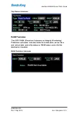
Page 237: ...m 5 13 Trip Planner Calculator RAIM Prediction The GPS RAIM Receiver Autonomous Integrity Monitoring Prediction calculator includes fields for destination arrival time and arrival date and will produc...

Page 238: ...maximum ground speed and average ground speed value providing options to reset each computation individually or a master reset to reset all The trip statistics will continue to compute each data field...

Page 239: ...list edit mode by highlighting the Edit box in the top right corner of the page either by touching it or using the bottom right AeroNav knob to highlight the box The edit box will be displayed with a...

Page 240: ...ecklist edit mode by touching the Edit box again or using the bottom right AeroNav knob to select it and then pushing the knob This will produce an empty gray checklist step item Touch or use the bott...

Page 241: ...oNav knob to insert the step in the desired location When done with editing the existing checklist touch select the Edit button again to exit edit mode Press the CLR button on the bezel to return to t...

Page 242: ...s will also toggle the Checklist Complete text back to Checklist Not Completed Resetting Checklists To quickly reset a completed or partially completed checklist press and hold the bottom right AeroNa...

Page 243: ...ursor to the next one Repeat the process as needed until all checklists are reset TIPS AND TECHNIQUES Backup Your Checklists For a variety of reasons including copying onto other AeroNavs restoring po...

Page 244: ...or the two dedicated COM slots in the top left corner or a combination of both Selecting preset datablock configurations is accomplished using the Datablock LSK on the SETUP tab of the AUX page and se...

Page 245: ...Speed above GPS CDI along the right side Left Block Default Displays two COM frequencies above two NAV frequencies above the Decoded VLOC IDENT block above the Nav Mode along the left side Top and rig...

Page 246: ...AUX page and selecting Setup as the option Once on the Datablock Setup page use the right outer knob to select the desired page location middle of top strip in the example below and the inner knob to...

Page 247: ...nd then touching the item in the center options list will place the touched item in the selected slot The datablocks on the right edge of the display are touch scrollable as well meaning many more dat...

Page 248: ...e Active and 1 Standby Nav frequencies in slots 3 and 4 2 lines Com Nav Standby 2 Provides a means to display a third com or nav frequency second standby slot 2 lines Only available on left side datab...

Page 249: ...the mode e g Normal Above Below etc can be toggled by either using the adjacent bezel LSK if on the left side of the AeroNav or by touching the lower 1 3 of the block If selected for display on the le...

Page 250: ...aypoint and the aircraft position direction of flight at the time of waypoint activation track may not necessarily be a straight line but include a button hook at the beginning Next Waypoint Informati...

Page 251: ...from present position to the designated waypoint 5 lines Note to change the designated waypoint touch the datablock which generates a keyboard Type in the designated waypoint identifier and press Ent...

Page 252: ...e to the destination from present position 2 lines To Waypoint Direct Info Active To waypoint identifier bearing from present position to active waypoint straight line distance from present position d...

Page 253: ...along flight planned route to the Destination waypoint 2 lines on side 1 line on top To Waypoint ETE Estimated time enroute to the To waypoint 2 lines on side 1 line on top GPS CDI Current track desi...

Page 254: ...current flight plan leg 2 lines on side 1 line on top Next Desired Track Desired track for the next flight plan leg not the active flight plan leg 1 line Vertical Speed Required Vertical speed require...

Page 255: ...Decoded VLOC IDENT For VORs Navaid identifier navaid radial currently on distance to navaid 3 lines For ILS Localizers Localizer identifier airport runway 3 lines Nearest Airport Nearest airport iden...

Page 256: ...rectangle around ownship position 2 lines on side 1 line on top Ground Speed Ground speed 1 line Ground Track Ground Track 1 line Wind Vector Wind speed and direction and an arrow indicating direction...

Page 257: ...riate fuel flow system Local Time Local time in HH MM SS format 2 lines on side 1 line on top UTC Time Zulu Time in HH MM SS format 1 line Flight Timer Flight timer in HH MM format 2 lines on side 1 l...

Page 258: ...s dependent on unit type selection made in User Options list as sent by the aircraft fuel flow system For twin engine aircraft this is the summed total 2 lines Fuel Used Estimated fuel used units depe...

Page 259: ...Datablock Setup page and then accept the green Confirm dialog box that gets displayed or use the Presets selection in the Datablock LSK TIPS AND TECHNIQUES Selecting Desired Datablocks If a desired d...

Page 260: ...l section provides a means to turn the map compass rose on off and to command the map declutter algorithm as to whether to use the altitude filter as well as a means to turn the heading track digital...

Page 261: ...same in dual AeroNav installations Transition Altitude and Level editing Controlled airspace alerts TFRs alerts and Special Use Airspace SUA alerts Modifying list of selectable procedures for the FMS...

Page 262: ...bottom right AeroNav knob is used to select a given row and twisting the inner ring of that knob will cycle through the options User Options Restoring factory defaults is accomplished by pressing the...

Page 263: ...ed using larger fonts Note that this selection may cause some datablocks to be removed because they will not fit in the available space Touch Screen On all touch screen controls are enabled Off all to...

Page 264: ...ay backlighting will rely on the ambient light sensor in the bezel until a low threshold is reached at which time it uses the dimming bus DimBus the LCD display backlighting will only be responsive to...

Page 265: ...field to automatically determine whether the system is using Day mode or Night mode for chart depiction Chart Auto Mode Sensor uses the ambient light sensor embedded in the bezel to determine if the C...

Page 266: ...d every 30 min 45 min Switch Tanks CAS message issued every 45 min 60 min Switch Tanks CAS message issued every 60 min Time Format UTC displays all times in the system in zulu time format 12 Hr displa...

Page 267: ...omatically calculated offset based on current location This should be manually readjusted if crossing time zones Current Time Just a display of current local time for reference Keyboard Convenience On...

Page 268: ...the specified WiFi network configuration defined in Maintenance Mode see page 7 72 The following are unauthorized for use see page 7 77 Remote Wired The AeroNav will use the wired ethernet interface a...

Page 269: ...wish to delete and press the bezel CLR button Push the bottom right knob again to exit edit mode Note This selection is only available if the system is configured to communicate with a remote mount M...

Page 270: ...map will be displayed in track up orientation Note Even though Heading Up is the default selection if there is no heading source then the default reverts to Track Up Potential heading sources include...

Page 271: ...regardless of SBAS In a non SBAS environment if one of those kinds of approaches is selected and it has a published flight path angle in the database then expect LNAV V Off Will not transmit glideslop...

Page 272: ...le Missed On Automatically activates the published missed approach when crossing the Missed Approach Point MAP Off Will not automatically activate the published missed approach and requires manual act...

Page 273: ...issued during FLTA caution conditions Terrain Warning Aural Terrain Pull Up Terrain Pull Up When selected that is the aural alert issued during FLTA warning conditions Terrain Terrain Pull Up Pull Up...

Page 274: ...les aural alerting of airspace 500ft Callout Aural On Enables 500 AGL based on GPS altitude aural callout when descending through 500 AGL Off Disables 500 AGL callout Bearing Reference Magnetic Sets m...

Page 275: ...ayed in statute miles and speed units will be displayed in miles hour Altitude Vert Speed Units ft fpm altitude units will be displayed in feet and vertical speed units will be displayed in feet min m...

Page 276: ...nits Gal fuel units will be displayed in gallons Lit fuel units will be displayed in liters Imp Gal fuel units will be displayed in Imperial Gallons Position Units ddd mm ss position units will be dis...

Page 277: ...Hide Page Tabs Never The page tabs will always be present After 2s the page tabs sink down out of view 2 seconds after they were last used After x s where x choices are 5 10 or 15 seconds the page ta...

Page 278: ...er ID row on the User Options page from the AUX Setup tab and then rotate the inner knob to cycle through the different user ID definition sets No further action is required to select the desired user...

Page 279: ...L MANAGEMENT The Fuel Mgmt LSK will be displayed if the AeroNav has been configured to communicate with an installed aircraft fuel flow system Fuel Management Dialog Box When properly configured and s...

Page 280: ...atus page if datalink is installed and properly configured GPS status page and the AeroNav databases status page Pushing the adjacent bezel key or touching the label soft key will cycle through the va...

Page 281: ...oads and Updates Procedures for downloading AeroNav data logs and for updating AeroNav databases and software are covered later in this manual Database Status Page The Databases selection on the Statu...

Page 282: ...date Databases LSK will put the AeroNav into Maintenance Mode where the databases can be uploaded to the AeroNav see page 7 55 for instructions GPS Status Page The GPS selection will provide a number...

Page 283: ...ng the AeroNav is compatible with other GNSS constellation systems such as Galileo Europe GLONASS Russia or Compass China The GPS navigation states possible are GPS Navigation State Operational Meanin...

Page 284: ...or satellite health or maintenance information is available in the satellite data stream However there may be times or geographic locations in the world where it is desirable to manually de select a s...

Page 285: ...is not authorized for that subscription level A status of Not Rcvd indicates that the data has not been received A status of None Xpctd indicates that not only has the data not been received but also...

Page 286: ...nd SIGMETs from that station The look ahead range is the radius for which a given product is provided from that station Each FIS B station periodically broadcasts a Current Report List CRL that indica...

Page 287: ...been received over FIS B Using the right knob or the touchscreen a cursor can be moved to surround each of the TFRs in the list Selecting one of the TFRs either by pressing the right knob button press...

Page 288: ...ver FIS B Using the right knob or the touchscreen a cursor can be moved to surround each of the reports in the list Selecting one of the AIRMETs or SIGMETs either by pressing the right knob button pre...

Page 289: ...n either the ADS B TFRs page or the ADS B AIRMET SIGMETs page this page will not be populated and will instead show No Text Selected at the top of the page Once one of those reports has been selected...

Page 290: ...ge shows the contents of the FIS B Product Updates Unavailable Report That report provides notification to users of outage of individual FIS B product updates or the entire FIS B service If 20 minutes...

Page 291: ...tab that was selected in the AUX subsystem Systems Alerts Tab Each section in the page is organized into three columns Short Text A short description of the condition This text also appears in the mes...

Page 292: ...AeroNav 900 880 Series Pilot s Guide 89000039 010 5 68 Aux Subsystem Rev 1 May 2019 Blank Page...

Page 293: ...rtified GPS that has been specifically designed to support single pilot IFR operations It has been designed for both retrofit and clean installations meaning that it can have different capabilities de...

Page 294: ...s no form of external CDI HSI or EFIS in the airplane and therefore no external course input available to the AeroNav VFR operations only No way to externally set course All course setting is conducte...

Page 295: ...w capability of the course on the AeroNav The nav source knob button is used only to toggle between the available states Nav source modes available GPS VLOC GPS VLOC OBS OBS VLOC Non cooperative elect...

Page 296: ...t are set on the external device s Nav source modes available None the nav source knob button will appear to be non functional NOTE Manual Sequencing May Be Required In Electro mechanical installation...

Page 297: ...l CDI or RMI or HSI indicator VLOC and GPS course and deviation data may all be coming into the AeroNav continuously but the channel selector acts as a filter to determine which one gets used in the n...

Page 298: ...h the approach type when the leg to the FAF becomes active and either the approach is VTF or the course to the FAF is within 45 of the final approach course GPS LPV Or LNAV VNAV LP V LP LNAV LNAV V Ba...

Page 299: ...ransmitted by the AeroNav is reactive to the external course setting knob or the Nav Source knob if no external course control is present or when a KI 208A or KI 209A is present for the inbound outbou...

Page 300: ...on board systems BendixKing strongly recommends practice operations in VMC conditions before any use in IMC to understand the level of integration between the AeroNav and the other on board systems an...

Page 301: ...in green then pushing the Nav Source knob will have no effect When one of them is the active Nav state pushing the Nav Source knob will toggle between the two states NOTE OBS Can Not Be Activated Ins...

Page 302: ...ft course to the fix is greater than or equal to 90 the system will activate the reciprocal course away from the station with guidance away FROM the fix The previously active TO leg will change to whi...

Page 303: ...station OBS FROM Depiction TIPS AND TECHNIQUES OBS Final OBS mode can be used to create a user defined course into a waypoint fix or an airfield Once in OBS mode use the external course knob to set t...

Page 304: ...ut do depict a 200nm OBS course line leg in Release 10 1 1 0 and later Changes can take up to 7 seconds to display on the map and east west legs may show some curvature NOTE OBS Behavior in Dual AeroN...

Page 305: ...capable of transmitting course The radial lines will be displayed once the VOR station is decoded and will be 50nm long The line will be green for the inbound course radial to the VOR when the aircraf...

Page 306: ...rn green and begin to flash The mode will flash for approximately five seconds and then turn green When the green indication stops flashing the AeroNav will be in the new nav mode To trigger the trans...

Page 307: ...e flight plan is part of a published missed approach and you were conducting a Vectors To Final approach Selecting this option will activate the first leg of the VTF approach i e the leg into the FAF...

Page 308: ...F The leg after the hold will become active Sequence Leg Displayed when there is no altitude source and the active leg terminates at an altitude Pressing the LSK upon reaching the altitude is required...

Page 309: ...ction required If the last waypoint before the approach were not the same as the IAF then a discontinuity would precede the approach The typical course of action in that case is to close the gap and t...

Page 310: ...x seconds where xxx is the course and x is the number of seconds left until the turn When the next leg is a hold however the alert text shows the entry type It will be Teardrop Entry or Parallel Entr...

Page 311: ...proach the FMS will auto tune the navaid that defines the final approach If the active leg is not part of a VHF based approach and if the active leg has a recommended navaid in the nav database the FM...

Page 312: ...titude can be manually set on the FMS Setup page by twisting the inner ring of the bottom right knob or by typing in a value in the virtual keyboard Each click of the inner ring adjusts the value by 1...

Page 313: ...e Once issued the alert will not be eligible to be issued again unless the aircraft has descended more than 500 feet below the transition altitude Likewise the transition level advisory CAS message is...

Page 314: ...gation Mode CDI Full Scale Value Enroute 2 0 NM 5 0 NM for non WAAS Terminal 1 0 NM Approach 0 3 NM or 2 whichever is less at the FAF In order to prevent abrupt changes to CDI deflection especially im...

Page 315: ...AeroNav 900 880 Series Pilot s Guide 89000039 010 Rev 1 May 2019 Navigation 6 23...

Page 316: ...displayed just above the FMS leg into the FAF As soon as the Activate Approach button is pressed the leg into FAF becomes active magenta and Vectors to Final is displayed just above that leg NOTE Disp...

Page 317: ...proach A discontinuity is an indication that the FMS doesn t know how to get from the leg before the discontinuity to the leg after In other words there s a gap in the flight plan The gap can be close...
Page 318: ...th the proper inbound course set including on localizer or ILS approaches where the course pointer is just for reference the course and glide slope deviation data will be transmitted as appropriate fr...

Page 319: ...e flown when OBS has not been selected using the nav source button NON PRECISION APPROACHES As with the case in precision approaches as long as the published approach is entered into the FMS as part o...

Page 320: ...e AeroNav WAAS capable If non WAAS the following procedures do not apply When GPS has been selected as the nav source and one of the RNAV GPS approach types with vertical guidance LPV L VNAV LNAV V LP...

Page 321: ...navigation as LNAV but also typically presents an ILS GS like presentation on the external deviation indicator The GPS draws a 3 D picture of the approach based on crossing the FAF at the depicted alt...

Page 322: ...LP Localizer Performance These approaches have localizer performance but no vertical guidance associated with them Use the published LP minimums The Nav Mode datablock will display LP for the approac...

Page 323: ...igned with the final approach course i e an angled entry to the FAF the pilot should ask the ATC controller to clarify if those vectors are to extended final or the published offset inbound leg to the...

Page 324: ...r to the MAP Alternatively the system can be configured to automatically enable the published missed approach for an active procedure by selecting the Auto Enable Missed selection in the User Options...

Page 325: ...AeroNav 900 880 Series Pilot s Guide 89000039 010 Rev 1 May 2019 Navigation 6 33 Enable Missed LSK Enabled Missed Approach in Flight Plan...

Page 326: ...imb attitude and consider using the autopilot to smoothly execute the assigned climb out or published missed approach procedures The Nav Source will automatically toggle back to GPS shortly after cros...

Page 327: ...ach the L2 LSK displays Retry Approach Pressing the L2 LSK will put the same VTF approach in the FMS flight plan with the inbound leg to the FAF active NOTE Activating Missed Approach Past MAP If the...

Page 328: ...he autopilot As another example some autopilots such as the KAP 140 and the KFC 225 do not support automatic switching to VLOC switching the nav mode and entering the in bound course must be manual op...

Page 329: ...approach procedures using the following lines of minima o LNAV minima including when using advisory vertical guidance from the system o LNAV VNAV minima o LPV minima o LP minima when installed with a...

Page 330: ...tring of A1 RNP10 Oceanic may require a LOA B2 RNAV 5 Enroute C2 RNAV 2 RNAV Q Routes and T Routes over land D2 RNAV 1 Terminal L1 RNP4 Oceanic may require a LOA O2 RNP1 Terminal S1 RNP APCH RNAV and...

Page 331: ...uding Handling system failures Operations at night Operations under hot cold temperatures Operations with high low power Operations using gloves Charging from the USB port Integration with the IFD100...

Page 332: ...bottom edge of the bezel Each time a new Warning or Caution or Advisory condition exists the AUX lamp will flash the appropriate color until either it is acknowledged by the pilot or the condition goe...

Page 333: ...op of cyan advisories Warning Message Pressing the CLR bezel key or touching the message bar on the display will acknowledge the message but will not do anything else After all active messages have be...

Page 334: ...e example below Long text Detailed explanation of the conditions that may cause the alert and in some cases a recommended action to be taken Note that an asterisk to the left of the detailed explanati...

Page 335: ...mum design temperature and reliability cannot be ensured until the unit is tested by the BendixKing Service Center Contact the BendixKing Service Center or a local dealer for service This message will...

Page 336: ...lution and determine the best course of action but if on an approach a Missed Approach is recommended Position updated via dead reckoning The system will use the last known position and groundspeed an...

Page 337: ...the appropriate minima GPS integrity is insufficient for LPV Approach Transition to a non LPV approach and the appropriate minima GPS integrity is insufficient for LP Approach Transition to a non LP a...

Page 338: ...the distance in nautical miles The long text omits Low High and instead shows target altitude in feet This is a traffic advisory with bearing information Establish visual contact with conflicting tra...

Page 339: ...Traffic will be the distance in nautical miles This is a traffic advisory with no relative altitude information and no bearing information Establish visual contact with conflicting traffic in order t...

Page 340: ...ider adding a source of cooling and or improving air flow in and around the AeroNav Backlight reduced to 25 Main supply voltage has fallen to approximately 11VDC Check the aircraft alternators are on...

Page 341: ...the remote transponder for greater than 2 seconds Contact the BendixKing Service Center if this persists across power cycles Radar Heavy Echos Ahead Generated when a number of red and or magenta echo...

Page 342: ...t are shown TIS Traffic Removed TIS traffic communications have ceased for more than 12 seconds TIS Traffic Unavailable No TIS ground station is available or communications have ceased for more than 6...

Page 343: ...elocity quality parameters drop below required accuracy limits A bing bong chime is played if this condition occurs Contact the BendixKing Service Center if this persists across power cycles TAWS Fail...

Page 344: ...ale Stale periods vary with weather product See the AeroNav product page on https www bendixking com en products aeronav gps navigators for detailed datalink product information No p No p products hav...

Page 345: ...error If the problem persists across a power cycle of the AeroNav contact the BendixKing Service Center for service Route Not Stored The route cannot be internally stored due to an internal error If...

Page 346: ...d track of the next leg xx is the number of seconds before the start of the turn and counts down from an initial value For turns up to 120 the initial value is 10 seconds For turns more than 120 the i...

Page 347: ...ch is not authorized for GPS overlay the aircraft course is within 45 degrees of the final approach course the course to the active waypoint is within 45 degrees of the final approach course the dista...

Page 348: ...tenna config Recommend cycling power to the lightning sensor If the problem persists contact a local dealer for service Lightning sensor recoverable fault cc If the problem persists contact a local de...

Page 349: ...d and configured to share data between the units but there is no communication between the AeroNavs If both units are powered on contact the BendixKing Service Center or a local dealer for service Tim...

Page 350: ...e name Lower Altitude Limit Upper Altitude Limit FT The aircraft will intercept an airspace within 5 minutes 30 seconds This advisory can be enabled or disabled on the FMS setup page Airspace will be...

Page 351: ...av performance such as datalink and GPS acquisition will be degraded Contact the BendixKing Service Center for service AeroNav Requires Service Contact the BendixKing Service Center for service Lightn...

Page 352: ...he hold fix xxx is the holding inbound course Teardrop Entry The next leg is a hold with a teardrop entry and there are 30 seconds or less until the aircraft reaches the hold fix Parallel Entry The ne...

Page 353: ...played for 5 seconds and then removed Waypoint Upload Rejected A user waypoint has been received from an external source e g WiFi but the waypoint was rejected as invalid Possible causes includes a re...

Page 354: ...ype of AeroNav being used The message is displayed for 5 seconds and then removed Radar fault code codes The sensor is reporting the non major fault codes that are shown Traffic Information Incomplete...

Page 355: ...s Guide 89000039 010 Rev 1 May 2019 General 7 25 UTC Time Mismatch Please restart AeroNav when possible The internal clock does not match the time received from the GPS Power cycling the AeroNav will...

Page 356: ...Glideslope Vertical Deviation Half scale up deviation flag stowed Annunciators All on Bearing to Waypoint RMI 135 Selected Course OBS 150 when interfaced to an HSI with course pointer Desired Track 15...

Page 357: ...rcuit breakers which need to be pulled out to remove power to an AeroNav or the top left AeroNav knob can be pushed and held to power the unit down recommended method LOSS OF AERONAV Failure Indicatio...

Page 358: ...Support to coordinate for a repair action LOSS OF DISPLAY Failure Indication The first indication that an AeroNav has experienced a loss of the display LCD is the appearance of a black display but th...

Page 359: ...erform all other functions that are still available Consider cycling power on the affected AeroNav via the top left power knob After the flight notify an BendixKing Service Center or BendixKing Custom...

Page 360: ...k has not been reacquired the system will transition to No GPS and provide the appropriate CAS message and remove the ownship symbol from the moving map All GPS based navigation should remain unaffect...

Page 361: ...ffected AeroNav may be resumed After the flight notify an BendixKing Service Center or BendixKing Customer Support to coordinate for a repair action OTHER ANOMALIES Other system anomalies are indicate...

Page 362: ...stacle and Chart data are supplied by Jeppesen via JDM subscriptions Refer to the Jeppesen product website for the various geographic and bundling options available For those aircraft equipped with ex...

Page 363: ...ch AeroNav individually controls the bezel brightness backlighting of knobs and buttons through a set of available options Manual Control Dimming Bus Control Use Ambient Light Sensor on the User Optio...

Page 364: ...who prefer to remove the display of terrain from the map during night operations use the Land part of the map declutter LSK to deselect terrain from being displayed NOTE Chart Data Reliance Always re...

Page 365: ...esign is that the metal bezel is intentionally designed to radiate heat away from the internal components and out of the unit This can have the effect of a bezel that may be warm to the touch This is...

Page 366: ...atures responsiveness of the display and to touch or bezel input may take longer than normal until the AeroNav has warmed up WARNING AERONAV 910 905 ONLY Very Cold Temperatures May Damage Sensors Ther...

Page 367: ...ng maximum values are reduced 10 9VDC VHF radio output power reduces to 6W 10 0VDC VHF radio output power reduces to 4W 9VDC 60 second countdown to AeroNav shutdown begins countdown message displayed...

Page 368: ...RATIONS The following actions are taken as input power is increased to the AeroNav Input Voltage AeroNav Operation Impact 32 3VDC VHF radio shuts down to protect itself from over voltage events Note t...

Page 369: ...the skin from the glass The thinner the glove or the more compatible the material e g leather fine cotton etc the greater the likelihood of success will be Likewise the more surface area that comes in...

Page 370: ...esent page and verify the AeroNav changes to the selected tab Pass Fail With the FMS FPL tab displayed use touch to type in a typical flight plan and verify that all entries were recognized Pass Fail...

Page 371: ...TURE Charge Devices From the AeroNav USB Port Most USB devices can be charged directly from the USB port on the front bezel of each AeroNav while on the ground or in flight This can be very handy if u...

Page 372: ...from the IFD100 mobile app Up to two IFD100 apps can be connected to a panel mount AeroNav at a time over WiFi The IFD100 application can be downloaded as a free download from the Apple Store It does...

Page 373: ...exit demo mode and proceed into normal flight mode Demo mode can also be exited by removing the USB fob and cycling power to the AeroNav While in demo mode the AeroNav will fly the active flight plan...

Page 374: ...utes for direct legs but changes to altitude constraints in terminal area procedures will not be retained in stored routes TIPS AND TECHNIQUES Flight Above Terrain in Demo Mode To ensure flight above...

Page 375: ...av TIPS AND TECHNIQUES Some Elements Simulated in Demo Mode Some aspects of AeroNav behavior are completely simulated in demo mode For example on models equipped with a VHF radio the radios can be tun...

Page 376: ...d at https www bendixking com en products aeronav gps navigators Data that can be transferred is expected to grow over time but the basic functions are summarized in the table below Data Transfer Desc...

Page 377: ...Nav and or can be created on the AeroNav and transmitted off board for third party device application use WiFi Traffic Traffic data known by the AeroNav TAS sensor TIS receiver TIS B receiver etc is s...

Page 378: ...device application use WiFi USB Instrument Approach and Transition Instrument approach and selected transition data is streaming out of the AeroNav to facilitate automatic chart and transition selecti...

Page 379: ...ivating function keys page keys changing map range volume etc via the paired keyboard Inbound to AeroNav only Bluetooth Data Logs Datalogs can be downloaded from an AeroNav onto a fob device for impor...

Page 380: ...tenna or by connecting the equipment to a different circuit than the affected equipment Consult an authorized dealer or other qualified avionics technician for additional help Operation of this device...

Page 381: ...e celui de l quipement concern Consultez un installateur agr ou un autre technicien en avionique qualifi pour obtenir de l aide suppl mentaire L utilisation de cet appareil est soumise aux conditions...

Page 382: ...TENANCE MODE AT POWER UP If the AeroNav is powered off maintenance mode can be started by inserting a USB fob into the USB port located on the front panel of the AeroNav Once the fob has been inserted...

Page 383: ...AeroNav 900 880 Series Pilot s Guide 89000039 010 Rev 1 May 2019 General 7 53 Download Logs LSK Confirm Cancel LSKs...

Page 384: ...to maintenance mode the Update tab will be selected Update Databases LSK EXITING MAINTENANCE MODE To return to flight mode from maintenance mode select the Update tab either by touching that tab or by...

Page 385: ...ularly and that you ensure the databases are current prior to conducting flight operations The table below summarizes the database update periods Database Update Cycle Comments Source Chart Data 14 da...

Page 386: ...tml It is recommended to use drives between 4GB and 16B capacity To perform a data update ensure the data to be updated is placed onto one of the acceptable USB fobs and then start the AeroNav in main...

Page 387: ...em can be selected by touching the item surrounded by the cursor When an item is selected a checkmark will appear on the right side of the list Pressing the right knob button or touching an item when...

Page 388: ...display list Not doing so may extend data upload times considerably by uploading unintended files NOTE Do Not Power Off the AeroNav During Data Update Cycling power to the AeroNav during a database u...

Page 389: ...d be updated for each item to be loaded Upload progress bar Typical upload times are Worldwide Obstacles 1 5 MB 5 sec Eastern US Charts 100 MB 3min US Charts 180 MB 5 min Worldwide Charts 430 MB 13 mi...

Page 390: ...the load status of each item in the list If an item was not selected the status will be Skipped If an item was successfully loaded the status will be OK If an error occurred the status will be ERROR I...

Page 391: ...in a safe place If the USB fob is inadvertently left in the USB port during flight mode there will be no adverse affect as the USB fob is ignored during flight mode Once the AeroNav is back into flig...

Page 392: ...used for navigation or communication in the air or on the ground Use the Service Hotline defined on the inside back cover NOTE Database Accuracy and Completeness BendixKing accurately processes and va...

Page 393: ...he factory for any future software updates The BendixKing position is that any shop that holds a repair station certificate an A P or an Experimental Aircraft owner with log book signoff authority can...

Page 394: ...of the FMS output and AeroNav state It logs at a rate of approximately 1Hz Flight Log This log provides a detailed record of your aircraft state as measured by the various AeroNav sensors It logs at a...

Page 395: ...ogs tab will already be active Insert a USB fob into the USB port Datalogs Download Page Maintenance Mode The Logs tab in maintenance mode shows a list in the center of the display containing the list...

Page 396: ...ent on the number and types of logs being downloaded and the length of time since the last download Times can range from a few seconds to more than 15 minutes The more often logs are downloaded the sh...

Page 397: ...le Power on True airspeed if available Turn rate if available Vertical speed if available Pressure altitude if available Lat Lon Engine Log Date Time stamp Fuel Remaining gal Power on Fuel Time Remain...

Page 398: ...onfigurations 47 GPS Antenna x System Configuration SW versions part numbers chassis ID 145 Dimming Settings 23 Aircraft Tail Number 1 Chart State validity dates identifier 6 Datablock selections 32 U...

Page 399: ...nerated on an AeroNav and backed up using this procedure Then they can be reloaded onto any AeroNav or multiple AeroNavs via this procedure User Data Save and Restore Options SAVING USER DATA Ensure a...

Page 400: ...stored user data is installed in the AeroNav Start the AeroNav in maintenance mode see Maintenance Mode section on page 7 52 From the Update tab ensure the dated file s of interest Restore data type Y...

Page 401: ...ies Pilot s Guide 89000039 010 Rev 1 May 2019 General 7 71 Selected but hasn t started yet Pending Save or Restore underway Active Save or Restore passed over Skipped Completed with no error OK Comple...

Page 402: ...d communicate with other devices that have also connected to that network The choice of configuration method depends upon what other equipment is onboard the aircraft Typically if you have a unit such...

Page 403: ...a client configuration this is the SSID of the network to which the AeroNav will connect PSK the network password For a WAP configuration this will be the password that connecting devices will have t...

Page 404: ...en and a small underline style cursor will appear below the character position that is being edited Rotate the right inner knob in either direction until the desired character is displayed Then rotate...

Page 405: ...uld be selected to make the AeroNav be the network WAP and Remote Wi Fi should be selected to connect the AeroNav as a client on another network TIPS AND TECHNIQUES If you sometimes connect your IFD10...

Page 406: ...me WiFi can be disabled by selecting Off NOTE When using the inner knob to select a WiFi configuration options for Local Wired Remote Wired and Static IP may appear Those options should not be selecte...

Page 407: ...using DHCP To configure the AeroNav in this manner only flight mode operations are required Restart the AeroNav in fight mode select the Aux page SETUP tab and then select the User Options LSK Using...

Page 408: ...AeroNav 900 880 Series Pilot s Guide 89000039 010 7 78 General Rev 1 May 2019 outer knob scroll down to the Networking option Then use the right inner knob to select Static IP...

Page 409: ...eing able to pair with one device at a time dual AeroNav installations should turn off Bluetooth in the User Options page on one AeroNav NOTE Acceptable Bluetooth Keyboards Due to certification constr...

Page 410: ...on the AeroNav After a while the AeroNav will discover the keyboard and it will appear on the list of devices shown on the screen At that point press the Stop Scan LSK After Stop Scan has been presse...

Page 411: ...AeroNav 900 880 Series Pilot s Guide 89000039 010 Rev 1 May 2019 General 7 81 Bluetooth pairing keyboard discovered Bluetooth pairing Pair Device LSK...

Page 412: ...AeroNav 900 880 Series Pilot s Guide 89000039 010 7 82 General Rev 1 May 2019 Bluetooth pairing pairing code...

Page 413: ...will be shown in green Bluetooth pairing pairing successful If the device is not shown in green or if the device name disappears from the display restart the pairing process with pressing the button o...

Page 414: ...board Bluetooth WiFi Confirmation Pop Up Test that the pairing was successful by any of several methods including Press FMS several times on the Bluetooth keyboard Verify that the FMS page changes wit...

Page 415: ...ff TIPS AND TECHNIQUES Physically Secure the Keyboard A common and effective technique to physically secure the keyboard in the cockpit is to apply Velcro to the back surface and find somewhere access...

Page 416: ...the keyboard is connected A flashing green LED indicates it is trying to pair A yellow LED is lit every time a keystroke is sent to the AeroNav While charging the red LED turns on and grows dimmer as...

Page 417: ...leaner directly on the screen In general isopropyl alcohol is a safe and effective cleaner Methanol and most acidic solutions can be toxic or damaging to glass coatings if misused Excessive or unneces...

Page 418: ...Rev C of the 190 00357 08 Garmin Install Manual AeroNav 880 500 500W 4 01 Main No HTAWS enablement This corresponds to Rev C of the 190 00357 08 Garmin Install Manual The following table represents th...

Page 419: ...S Other Audio Output Wiring to Audio Panel To take full advantage of FLTA and other AeroNav aural alerting e g TOD chime ensure the audio output signals are wired to the audio panel For 500 530 replac...

Page 420: ...019 TIPS AND TECHNIQUES Multiple Integration Options Discuss integration options with your installer There are several options that can be added to the system for added capability There is a dedicated...

Page 421: ...30 ARS 2 23 Audio Tab 5 2 Aural Alerts 5 49 500 foot callout 4 36 Auto VLOC Tuning 6 18 B Backlight Bezel 5 41 Display 5 41 Keyboard 1 45 Night Operations 7 33 Backup Restore 7 69 Before Takeoff 1 55...

Page 422: ...4 European VFR Charts 4 60 Excessive Descent Rate 4 41 Exocentric View 4 52 F Field Of View 2 2 2 15 FIS B 4 21 Flight Plan Activating 3 24 Approaches 3 30 Arrivals 3 30 Compact View 3 8 Creating 3 4...

Page 423: ...irtual 1 41 L Lateral Offset 3 25 Line Select Keys 1 9 LNAV 6 27 LNAV VNAV 6 27 LNAV V 6 27 Local Time Offset 5 43 LP 6 28 LP V 6 28 LPV 6 26 6 28 M Manual Sequencing 6 3 Map Decluttering 4 12 Panning...

Page 424: ...Nav 1 24 Satellite 5 4 Tuning 1 27 RAIM 5 13 Range To Altitude Arc 3 29 Retry Approach 6 33 RNAV 6 26 RNP 6 35 Route Preview 3 45 Rubber Banding 4 14 S Self Test 7 26 Setup Datablocks 5 20 FMS 5 38 Ma...

Page 425: ...ansition Level 6 19 Transponder Control 1 33 Datablock 5 21 5 26 Default Code 5 45 Wiring 7 89 U USB 1 13 7 46 7 55 Charging 7 41 User Options 5 39 User Settings 5 53 User Waypoints 3 49 As an airfiel...

Page 426: ...9201 B San Mateo Blvd NE Albuquerque NM 87113 U S A CAGE 6PC31 505 903 6148 Worldwide 855 250 7027 US Canada www bendixking com...

Reviews: