89000109-002
xVue Touch Installation Manual
Rev 2
Page 4-20
© Honeywell International Inc. Do not copy without express permission of Honeywell.
For Use in Non-Certified Aircraft
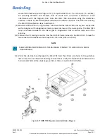
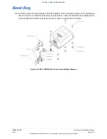
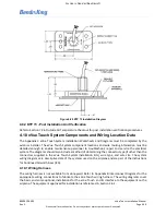
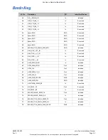
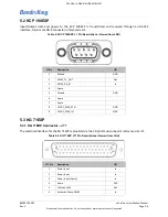
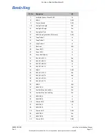
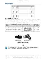
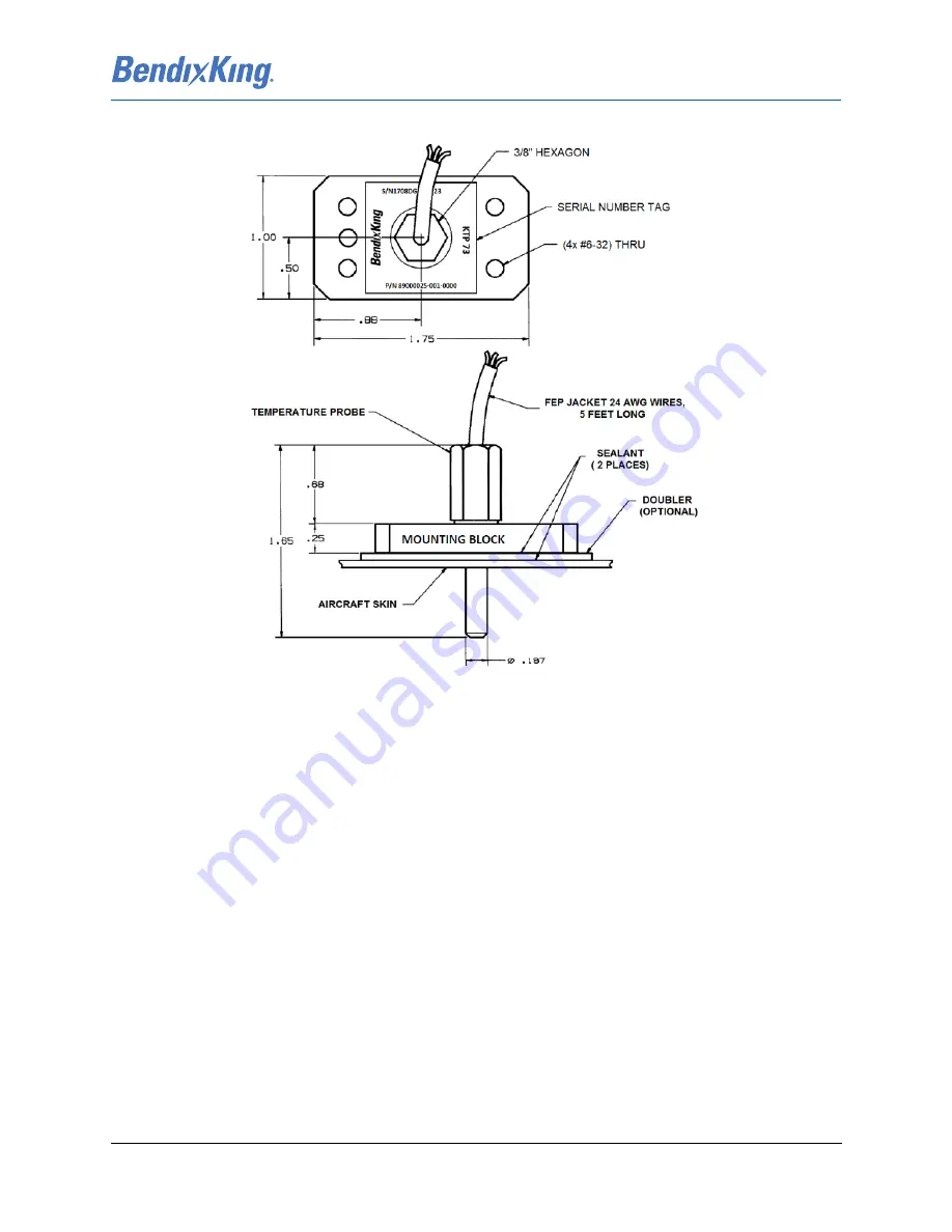
Figure 4-20 KTP 73 Installation Diagram
4.9.2 KTP 73 - Post Installation Unit Verification
Refer to Section 7.2.6 Outside Air Temperature Checkout for post installation verification procedures.
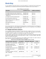
4.10 xVue Touch System Components and Wiring Location Data
The Appendix C xVue Touch System Installation Worksheets and Diagrams must be completed by the
avionics installer. The xVue Touch System component locations and wire routing information must be
detailed enough to enable maintenance personnel to troubleshoot, repair and service the electrical
system. The diagrams should also include a method of determining the connector type (if other than the
connectors supplied in the xVue Touch System Installation Kits), wire type, and wire size. The system
wiring diagrams are descriptive data of the systems used on the airplane and are part of the Instructions
for Continued Airworthiness (ICA).
4.10.1 Wiring Harness
The wiring harness is not available from Honeywell. Refer to Appendix B Interconnect Diagrams for the
appropriate wiring connections to fabricate the xVue Touch wiring harness. The wiring diagrams cover
the basic, and some optional, installations for the xVue Touch and its interface to the equipment on the
airplane. The equipment approved for installation is referenced in Section 3.6.1.

