


89000109-002
xVue Touch Installation Manual
Rev 2
Page 5-10
© Honeywell International Inc. Do not copy without express permission of Honeywell.
For Use in Non-Certified Aircraft
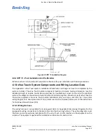
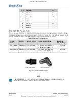
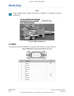
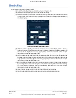
Figure 5-2 KMG 7010 Backshell
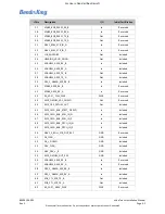
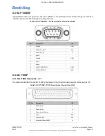
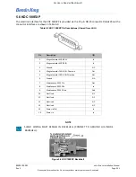
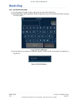
5.5 MD32
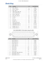
The electrical interface for the MD32 is provided via the 9 pin DB-9 connector Table 5-8.
Table 5-8 MD32 DB-9 Pin Descriptions (Viewed from LRU)
Pin
Description
I/O
1
Ground
GRN
2
Not Used
-
3
Reserved
-
4
Reserved
-
5
Power
-
6
ARINC B
Out
7
ARINC A
Out
8
Not Used
-
9
Not Used
-
NOTE
SHIELD WIRING MUST REMAIN IN BACKSHELL (CONNECT TO GROUND LUG INSIDE
BACKSHELL).