89000109-002
xVue Touch Installation Manual
Rev 2
Page 6-38
© Honeywell International Inc. Do not copy without express permission of Honeywell.
For Use in Non-Certified Aircraft
Load the KG 71EXP Configuration and Maintenance Tool (CMT) software application, available for
download on the BendixKing Website - Dealer Portal, onto a maintenance PC. Connect the Maintenance
PC to the DB-9 KG 71EXP maintenance port using the USB to Serial Converter/Adapter, refer to Section
5.3.3 and Figure B-7 for more information on the maintenance port and wiring. Proceed with the
configuration steps as outlined in the following sections.
6.3.1 KG 71EXP Maintenance Interface Configuration
The RS-232 Serial interface for maintenance purposes is dedicated to a specific RS-232 port. The
maintenance port is wired directly into the KG 71EXP main connector and must be accessible by the
technician to connect to the port. The maintenance port is connected to the maintenance PC via a USB to
RS-232 cable. The cable must support a baud rate of at least 115200 bits per second and must be long
enough to allow the PC to be easily operated by the technician. The KG 71EXP should be powered off
when the USB to RS-232 cable is connected to the maintenance port. The CMT application should be
started after the PC is connected to the maintenance port. Once the CMT application is running the PC
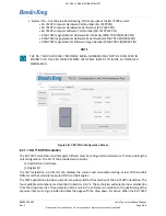
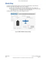
should display the startup screen as illustrated in Figure 6-46 CMT Startup Screen. The KG 71EXP can then
be powered on. If the KG 71EXP was already running when CMT application is started, then power must
be cycled on the KG 71EXP before continuing.
Figure 6-46 CMT Startup Screen
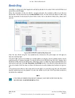
When the KG 71EXP is powered up, the CMT application will detect the KG 71EXP unit and initialize the
connection. Once communication is established, the CMT application will display the main configuration
screen with following four major tabs at the left side (see Figure 6-47 CMT Main Configuration Screen):
• KG 71 (Default active tab) – this tab allows setting of the KG 71EXP installation orientation,
detection of offsets and configuration of the unit I/O.
• KMG 7010 – this tab allows setting of the KMG 7010/MD32 installation orientation, entering of
the KMG 7010/MD32 offsets and provides a guide through the magnetometer compensation
procedure.
• Event Log – this tab provides list of logged events, actual number of power ups. The tab also
provides a mean to erase event log.


