89000109-002
xVue Touch Installation Manual
Rev 2
Page T-4
© Honeywell International Inc. Do not copy without express permission of Honeywell.
For Use in Non-Certified Aircraft
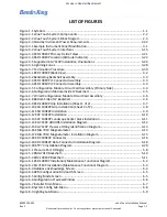
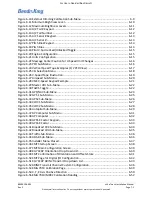
Figure 7-46 Restore Data to APM............................................................................................. 7-33
Figure 8-1 Screen Maint Menu................................................................................................... 8-7
Figure 8-2 Manual Touch Calibration Menu............................................................................... 8-7
Figure 8-3 Example of Touch Calibration Utility Screen ............................................................. 8-8
Figure 8-4 Example of the Touch Calibration Utility Test Screen ............................................... 8-9
Figure 8-5 Reverting Touch Calibration Screen ........................................................................ 8-10
Figure 8-6 Restore Def. Touch Cal. Screen ............................................................................... 8-10
Figure 8-7 Restoration of Default Values Successful Screen .................................................... 8-11
Figure A-1 KSD 100EXP Center of Gravity................................................................................... A-1
Figure A-2 KSD 100EXP Panel Cutout Dimensions...................................................................... A-2
Figure A-3 KCP 100EXP Dimensions and Center of Gravity - Portrait Orientation ..................... A-3
Figure A-4 KCP 100EXP Dimensions and Center of Gravity - Landscape Orientation................. A-4
Figure A-5 KCP 100EXP Panel Cutout Dimensions...................................................................... A-5
Figure A-6 KG 71EXP Dimensions and Center of Gravity............................................................ A-6
Figure A-7 KG 71EXP Mounting Hole Pattern Diagram .............................................................. A-7
Figure A-8 KMG 7010 Outline and Mounting Drawing (Sheet 1 of 2) ........................................ A-8
Figure A-9 KMG 7010 Outline and Mounting Drawing (Sheet 2 of 2 ......................................... A-9
Figure A-10 MD32 Outline Drawing ......................................................................................... A-10
Figure A-11 KDC 100EXP Outline and Mounting Drawing (Sheet 1 of 2) ................................. A-11
Figure A-12 KDC 100EXP Outline and Mounting Drawing (Sheet 2 of 2) ................................. A-12
Figure A-13 KTP 73 Dimensions and Center of Gravity ............................................................ A-13
Figure A-14 KTP 73 Mounting Hole Pattern ............................................................................. A-14
Figure A-15 KTP 73 Generic Doubler (for 0.016 - 0.032 Inch Skin Thickness) .......................... A-14
Figure B-1 xVue Touch Power Connection Diagrams ................................................................. B-1
Figure B-2 Autopilot Interconnect Diagram ............................................................................... B-2
Figure B-3 Weather and Traffic Interconnect Diagram .............................................................. B-3
Figure B-4 Navigation Interconnect Diagram ............................................................................. B-4
Figure B-5 Audio Panel Interconnect Diagram ........................................................................... B-5
Figure B-6 KSD 100EXP LRU Interconnect Diagram.................................................................... B-6
Figure B-7 KG 71 LRU Interconnect Diagram - 1......................................................................... B-7
Figure B-8 KG 71 LRU Interconnect Diagram - 2......................................................................... B-8
Figure B-9 KG 71 LRU Interconnect Diagram - 3......................................................................... B-9
Figure B-10 KG 71 LRU Interconnect Diagram - 4..................................................................... B-10
Figure C-1 xVue Touch System Components and Cable Routing (Top View) ............................. C-2
Figure C-2 xVue Touch System Components and Cable Routing (Side View) ............................ C-3
Figure C-3 xVue Touch System Circuit Breakers and Switch Locations ...................................... C-3

