89000109-002
xVue Touch Installation Manual
Rev 2
Page 6-44
© Honeywell International Inc. Do not copy without express permission of Honeywell.
For Use in Non-Certified Aircraft
6.3.1.3.4 Air Data
The transmit channel is be used to support air data values. This configuration sets transmit channel as
Low Speed A429. The KG 71EXP will send out the following labels:
(1) 162 – Density Altitude, transmit rate 5 Hz
(2) 203 – Altitude, transmit rate 20 Hz
(3) 204 – Baro-Corrected Altitude, transmit rate 5 Hz
(4) 206 – Computed Airspeed, transmit rate 20 Hz
(5) 210 – True Airspeed, transmit rate 20 Hz
(6) 211 – Total Air Temperature, transmit rate 5 Hz
(7) 212 – Altitude Rate, transmit rate 20 Hz
(8) 213 – Static Air Temperature, transmit rate 5 Hz
(9) 234 – Baro Correction (mb), transmit rate 20 Hz
(10) 242 – Total Pressure, transmit rate 20 Hz
(11) 245 – Static Pressure, transmit rate 20 Hz
(12) 271 – Air Data Discrete Status, transmit rate 5 Hz
6.3.1.3.5 Attitude Interface
The transmit channel can be configured to support existing systems with an attitude output only. This
configuration sets transmit channel as High Speed A429. The KG 71EXP will send out the following labels:
(1) 324 – Pitch Angle, transmit rate 80 Hz
(2) 325 – Roll Angle, transmit rate 80 Hz
6.3.1.3.6 Altitude Interface
The transmit channel can be configured to support existing systems with an altitude data set. This
configuration sets transmit channel as Low Speed A429. The KG 71EXP will send out following labels:
(1) 203 – Pressure Altitude, transmit rate 20 Hz
(2) 204 – Baro Corrected Altitude, transmit rate 20 Hz
6.3.1.3.7 Custom Configuration
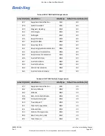
In addition to the pre-defined configurations, the KG 71EXP allows custom configuration of each transmit
channel. If this option is selected all the outgoing AHRS and Air Data labels listed in Table 6-5 and Table 6-
6 are available to be configured. If the Custom option is selected from the drop down menu, the
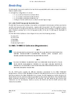
technician can customize both of the ARINC ADC transmit channel labels by pressing the
Edit Custom
button from the “Digital I/O” tab (shown in Figure 6-50 CMT Page for Digital I/O Configuration). The
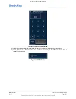
labels values are entered on the ARINC Transmit Channel Custom Configuration screen, shown in
Figure 6-52 below.
NOTE
IN THE DIGITAL I/O TAB OF THE CMT EITHER OR BOTH TX CHANNELS CAN BE SET TO
CUSTOM. IF ONLY ONE TRANSMIT CHANNEL IS SET TO “CUSTOM”, THE CUSTOM
CONFIGURATION OF THE OTHER TRANSMIT CHANNEL WILL BE IGNORED.
NOTE
CHANGES IN CUSTOM CONFIGURATION WILL BE DISCARDED IF THE “<BACK” LINK AT THE
LEFT-UPPER CORNER IS SELECTED INSTEAD OF “OK” SELECTION BUTTON.

