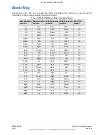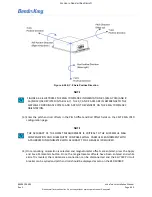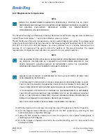
89000109-002
xVue Touch Installation Manual
Rev 2
Page 6-51
© Honeywell International Inc. Do not copy without express permission of Honeywell.
For Use in Non-Certified Aircraft
6.4.2 Magnetometer Compensation
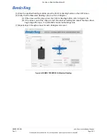
The “Required Heading” and “Measured Heading” fields become active after magnetometer calibration is
started. These fields display “--” before the calibration process is started.
The KG 71EXP uses a 12-points compensation procedure with 30 degree increments. The airplane needs
to be physically oriented during the procedure to the following magnetic headings: 360, 30, 60, 90, 120,
150, 180, 210, 240, 270, 300, 330 degrees. An airport compass rose or a landing compass with an
accuracy of ± 2 degrees will be used to place the airplane at the correct headings. The proper
magnetometer configuration and calibration is required for correct system operation.
(1) With the airplane on the compass rose, align the nose of the airplane to the North position.
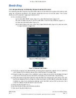
(2) Start the magnetometer calibration procedure on the CMT application by selecting the Start
Calibration button on the KMG 7010 page.
(3) Follow the CMT application display and rotate the airplane to the required heading value, it
should begin with 360 degrees.
(4) Once the airplane is physically oriented to the specified heading, wait 30 - 60 seconds for the
reading to stabilize.
NOTE
BEFORE THE MAGNETOMETER CALIBRATION PROCEDURE IS STARTED, THE KG 71EXP
ORIENTATION AND INSTALLATION OFFSETS MUST BE ENTERED AND SAVED. OTHERWISE
THE
HEADING
CALCULATION
PERFORMED
DURING
THE
MAGNETOMETER
COMPENSATION WILL BE ERRONEOUS.
NOTE
THE FOLLOWING PROCEDURES SHOULD BE COMPLETED WITH ENGINE(S) RUNNING AND
ALL AVIONICS ON. PERFORM AT A MAGNETICALLY UNDISTURBED PORTION OF THE
APRON. MAGNETIC HEADING SHOULD BE DETERMINED USING THE CALIBRATED
COMPASS ROSE AREA OR BY CALIBRATED MAGNETIC COMPASS.
NOTE
MAGNETIC FIELD STABILITY IS DETERMINED BY THE KG 71EXP FROM THE KMG 7010/
MD32 MAGNETIC VECTOR DATA.
IF THE MAGNETIC VECTOR DATA IS STABLE (VARIANCE OF INCOMING SIGNAL IS LOW),
THE KG 71EXP CALCULATES THE HEADING VALUE FROM THE MAGNETIC DATA AND THE
VALUE IS DISPLAYED IN THE MEASURED HEADING FIELD AS ILLUSTRATED IN Figure 6-55.
IF THE MAGNETIC VECTOR DATA IS UNSTABLE (IF THE MEASUREMENT IS DISTURBED),
THE CMT APPLICATION PROVIDES THIS INFORMATION TO THE TECHNICIAN TO REPEAT
STEPS. IF THE PROBLEM IS PERSISTENT, FOLLOW TROUBLESHOOTING PROCEDURES TO
REMOVE THE MAGNETIC DISTURBANCE, REFER TO SECTION 8.4.1.
WAIT 30 TO 60 SECONDS AT EACH HEADING FOR READING TO STABILIZE.

