


89000109-002
xVue Touch Installation Manual
Rev 2
Page 6-53
© Honeywell International Inc. Do not copy without express permission of Honeywell.
For Use in Non-Certified Aircraft
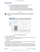
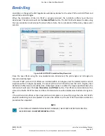
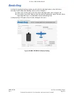
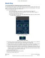
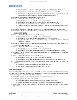
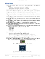
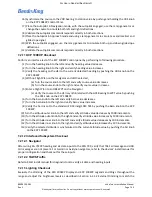
(8) When all required heading points are measured, the CMT application will report successful
completion of the magnetometer compensation, refer to Figure 6-56. Confirm storage of
parameters into the KG 71EXP NVM by pressing the Save button.
Figure 6-56 Completion of Magnetometer Calibration
(9) Exit the CMT application software and disconnect the maintenance PC from the KG 71EXP
maintenance port.
(10) Pull and reset the ADAHRS circuit breaker to cycle power on the KG 71EXP.
(11) Pull and reset the PFD circuit breaker to cycle power on the KSD 100EXP.
(12) With the KSD 100EXP in normal mode, verify the heading values, displayed on the PFD, orienta-
tion in 4 directions (North, 90, 180, and 270 degrees). Verify accuracy of ± 2 degrees of the air-
plane’s orientation and verify drift from each of the target heading values is not observed. This
satisfies the post installation heading check in Section 7.2.2 Heading Checkout.
(13) With engines running pneumatic pitch and roll standby instrument can be compared with KSD
pitch and roll for accuracy. This satisfies the post installation attitude check in Section 7.2.1 Atti-
tude Checkout.
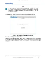
6.5 KTP 73 Configuration (Outside Air Temperature Probe)
There are no configuration settings for the KTP 73 Temperature Probe.
NOTE
ANY PREVIOUSLY ENTERED MEASURED PITCH AND/OR ROLL OFFSETS WILL REMAIN IN
THE KG 71EXP MEMORY UNTIL THE SAVE BUTTON IS SELECTED. RESELECTING THE KMG
7010/MD32 MOUNTING ORIENTATION TO THE ORIENTATION FROM WHICH EXISTING
OFFSETS HAVE BEEN GENERATED WILL RESULT IN THE DISPLAY OF THOSE SAVED PITCH
AND ROLL OFFSET VALUES.