

89000109-002
xVue Touch Installation Manual
Rev 2
Page B-5
© Honeywell International Inc. Do not copy without express permission of Honeywell.
For Use in Non-Certified Aircraft
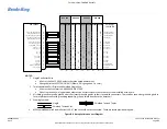
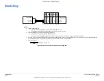
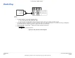
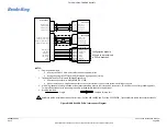
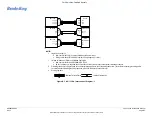
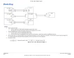
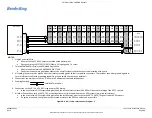
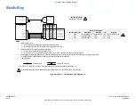
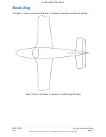
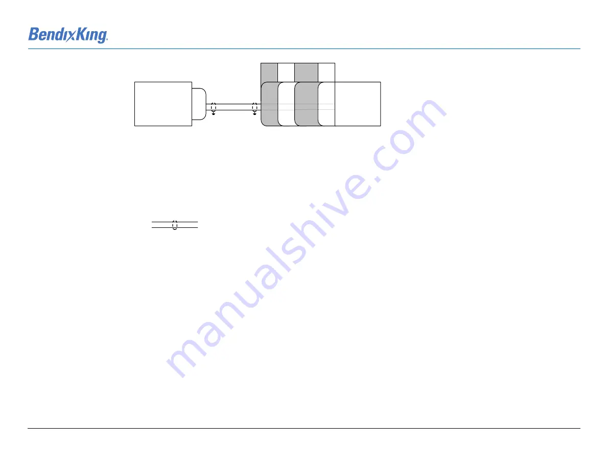
Figure B-5 Audio Panel Interconnect Diagram
J2
KSD 100
yW
KMA
30
KMA
28
J1
KMA 26
J1
KMA
24
P261
P241
AUDIO PANEL
46
AUDIO_ALERTS_OUT
47
AUDIO_ALERTS_OUT_REF
31 (29)
32 (43)
T (17)
14 (15) (16)
31 (32) (33)
T (17)
1
UNSWITCHED AUDIO HI
UNSWITCHED AUDIO REF
31 (29)
T (17)
14 (15) (16)
T (17)
32 (43)
31 (32) (33)
1
1
NOTES:
1
Twisted Shielded Pair/Triplet and Shielded Single Wire
x
All wires shall conform to ANSI/NEMA WC 27500
x
Do not remove any wiring between other active aircraft systems. Leave those systems installed as they are.
2
All shield grounds are to be grounded at the closest grounding point to their respective connectors . This includes connector grounding points.
For metallic backshells with grounding capability, ground shield directly to the backshell.
3 Connections shown in parentheses “()” denotes an alternate acceptable interconnect.
4 Drawing Symbols:
-
Shielded Twisted Pair


