89000109-002
xVue Touch Installation Manual
Rev 2
Page 3-18
© Honeywell International Inc. Do not copy without express permission of Honeywell.
For Use in Non-Certified Aircraft
thickness.
(3) If the original panel utilizes a tighter bend radius than the minimum bend radius appropriate to
material and thickness (refer to AC 43.13-1B, Chapter 4, Section 4), a softer material may be used
to match the original design and then heat treated to match the hardness and strength of the
original design. It is the installer’s responsibility to ensure the heat treatment has been properly
performed.
The instrument panel must be aluminum to meet the electrical bonding requirements between the KSD
100EXP unit and the airplane panel, reference Section 3.10.
The xVue Touch system equipment dimensions and installation templates are provided in Appendix A
Outline and Installation Drawings. Refer to AC 43.13-1B for edge distance guidance. For KSD 100EXP
mounting holes, refer to Appendix A Outline and Installation Drawings.
3.6.3 Standby Instruments
The xVue Touch System recommends a standby attitude indicator, airspeed indicator, and altimeter be
installed. If the indicator is used as the altitude/attitude source to a system that remains installed on the
airplane, it should be retained. In many cases the existing instruments may be retained for use as standby
instruments. Either two-inch or three-inch standby instruments may be used.
3.6.3.1 Standby Instrument Location
Standby instrument locations are recommended per AC 23.1311-1C, Section 15, to be within 35 degrees
from the pilot view centerline. This is within 21 inches (533 mm) from the reference center line, based on
a viewing distance of 30 inches from the panel.
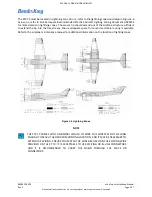
The preferred order, if the standby instruments are installed vertically is attitude indicator (top), airspeed
indicator, and altimeter (bottom). If there are space constraints the alternate vertical installation is
airspeed indicator (top), attitude indicator, and altimeter (bottom). The preferred order if the standby
instruments are installed horizontally is: airspeed indicator (left), attitude indicator, and altimeter (right).
If space limitations prevent the installation of the standby instruments either vertically or horizontally,
any order is acceptable provided the instruments are located within the recommendation of AC 23.1311-
1C.
3.6.3.2 Standby Attitude Indicator
For airplanes with an existing autopilot, the interfacing Attitude Indicator (AI) must be moved, if it is
located in the installation location required by the PFD. Since the AI is supplying attitude information to
the autopilot, it must be retained. The AI may be used as a standby indicator and may be relocated to an
NOTE
CERTAIN MODELS MAY REQUIRE A MOUNTING ADAPTER TO ACHIEVE THE MINIMUM
MOUNTING HOLE TO CUTOUT DISTANCE, PLEASE CONTACT BENDIXKING CUSTOMER
SUPPORT FOR ASSISTANCE.
NOTE
INSTALL THE STANDBY INSTRUMENTS IN PROXIMITY TO THE KSD 100EXP.

