89000109-002
xVue Touch Installation Manual
Rev 2
Page 4-10
© Honeywell International Inc. Do not copy without express permission of Honeywell.
For Use in Non-Certified Aircraft
4.4 KCP 100EXP Installation
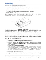
The KCP 100EXP is available in either a landscape or portrait configuration and may be installed directly in
the instrument panel, refer to Section 4.4.1, or in the center stack (for the landscape configuration), refer
to Section 4.4.2.
Refer to Section 4.10.1 for connections of the KCP 100EXP wiring harness. Overbraid is required for the
wiring interconnect between the KCP 100EXP and KSD 100EXP. Refer to Table 3-13 for the overbraid
specifications. For the instrument panel cutout dimensions, refer to Figure A-5.
4.4.1 KCP 100EXP Instrument Panel Installation Procedures
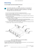
(1) Ensure all wiring and power checks have been completed per Section 6.1.
(2) Ensure airplane instrument panel has been prepared per Section 4.2.
(3) Ensure all power is removed from the airplane.
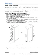
(4) Secure the DB-9 connector (J1) to the KCP 100EXP. Torque two jack post connector screws to 4 ±
0.4 in-lbs (0.45 ± 0.05 Nm).
(5) Verify the electrical bond between the backshell and the KCP 100EXP conforms to the guidelines
listed in Section 3.10 Electrical Bonding Considerations.
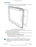
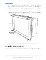
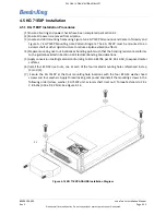
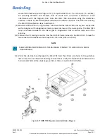
(6) Install the KCP 100EXP into the instrument panel using the four #4-40 captive socket head
mounting screws. Torque screws to 4 ± 0.4 in-lbs (.45 Nm).
Figure 4-12 KCP 100EXP Installation
(7) Verify the electrical bond between the KCP 100EXP and the instrument panel conforms to the
guidelines listed in Section 3.10 Electrical Bonding Considerations.
P1

