89000109-002
xVue Touch Installation Manual
Rev 2
Page 4-11
© Honeywell International Inc. Do not copy without express permission of Honeywell.
For Use in Non-Certified Aircraft
4.4.2 KCP 100EXP Center Stack Installation Procedures
(1) Ensure all wiring and power checks have been completed per Section 6.1.
(2) Ensure a location is available in the center stack for DZUS rail mounting the KCP 100EXP.
(3) Ensure all power is removed from the airplane.
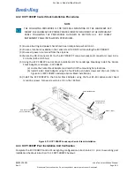
(4) Secure the DB-9 connector (J1) to the KCP 100EXP. Torque two jack post connector screws to 4 ±
0.4 in-lbs (0.45 ± 0.05 Nm).
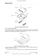
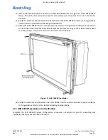
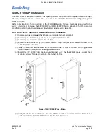
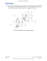
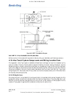
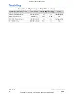
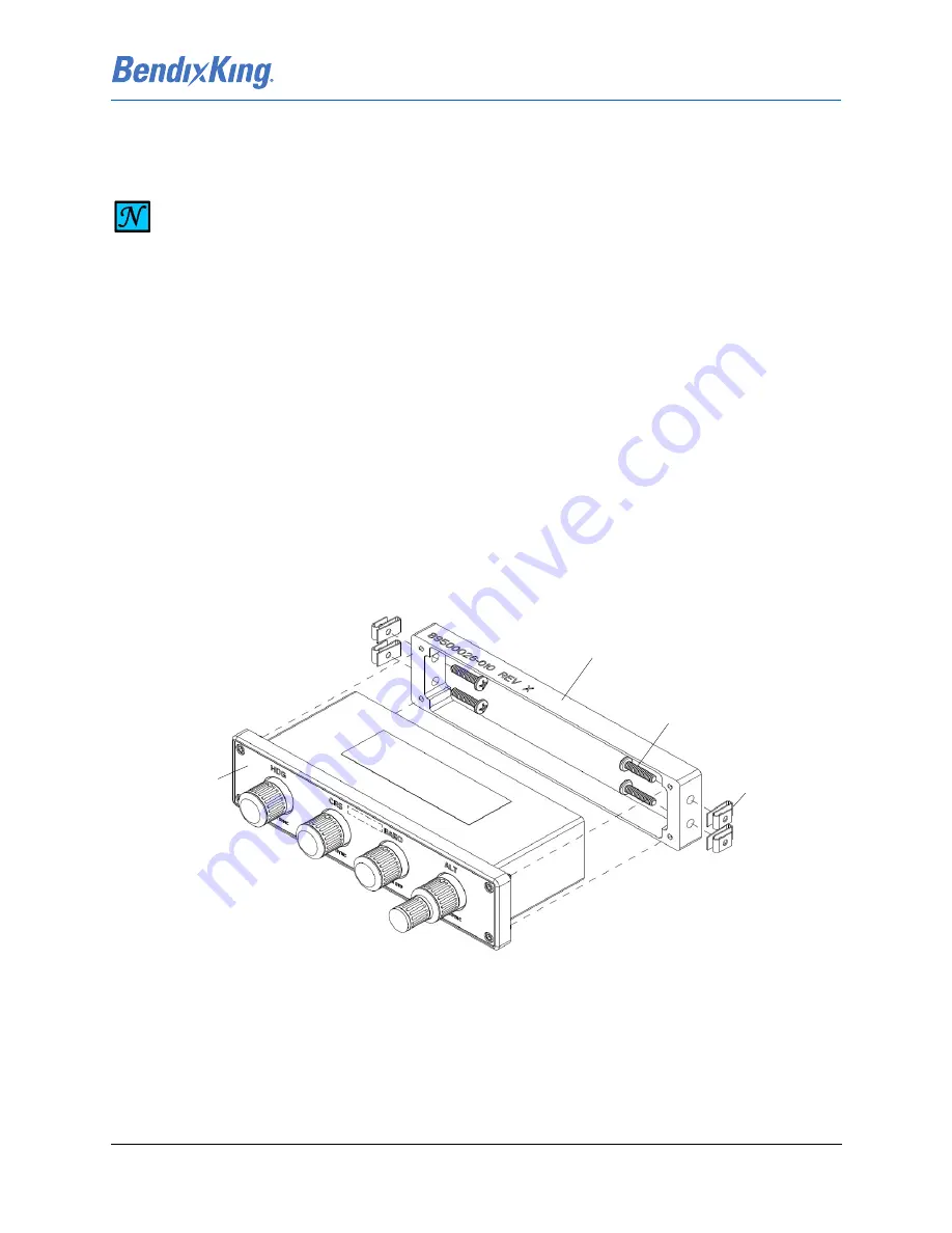
(5) Using the KCP 100EXP Control Panel Installation Kit for Landscape Mounting install the Center
Stack Adapter, Landscape – KCP 100EXP
(a) Locate the Center Stack Adapter and match drill the mounting hole locations.
(b) Install Center Stack Adapter using the four
#6-32 pan head screws and
clip nuts (refer to
Figure 4-13 KCP 100EXP Landscape Center Stack Installation).
(6) Install the KCP 100EXP to the Center Stack Adapter using the four #4-40 captive socket head
mounting screws. Torque screws to 4 ± 0.4 in-lbs (.45 Nm).
Figure 4-13 KCP 100EXP Landscape Center Stack Installation
4.4.3 KCP 100EXP Post Installation Unit Verification
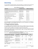
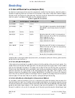
Complete the KCP 100EXP Control Panel lighting configuration in Section 6.2.1.1 prior to executing post
installation checkout in Section 7.2.11 KCP 100EXP Checkout.
NOTE
THE FOLLOWING PROCEDURE IS FOR DZUS RAIL MOUNTING OF THE LANDSCAPE KCP
100EXP. THE LANDSCAPE KCP 100EXP MAY BE DIRECTLY MOUNTED TO THE INSTRUMENT
PANEL FOLLOWING THE PROCEDURES OUTLINED IN SECTION 4.4.1 KCP 100EXP
INSTRUMENT PANEL INSTALLATION PROCEDURES.
Clip Nut (Qty 4)
#6-32 Pan Head
Screw (Qty 4)
Center Stack Adapter
KCP 100 Control
Panel (Landscape)

