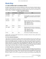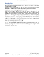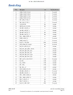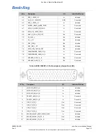
89000109-002
xVue Touch Installation Manual
Rev 2
Page 4-14
© Honeywell International Inc. Do not copy without express permission of Honeywell.
For Use in Non-Certified Aircraft
Perform the following Post Installation Checkout procedures:
(1) Section 7.2.10.1 Autopilot & KSD 100EXP Interface
(2) Section 7.2.10.2 Autopilot & KSD 100EXP Interface Checkout Procedures
(3) Section 7.2.1 Attitude Checkout
(4) Section 7.2.3 Leak Test
(5) Section 7.2.4 Altitude Display/Vertical Display and Standby Altimeter Checkout
4.6 KMG 7010 Installation
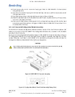
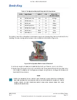
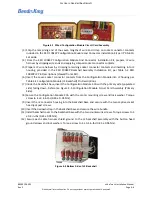
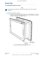
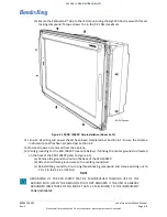
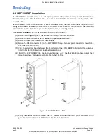
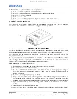
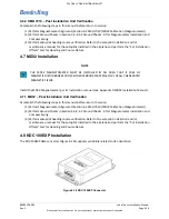
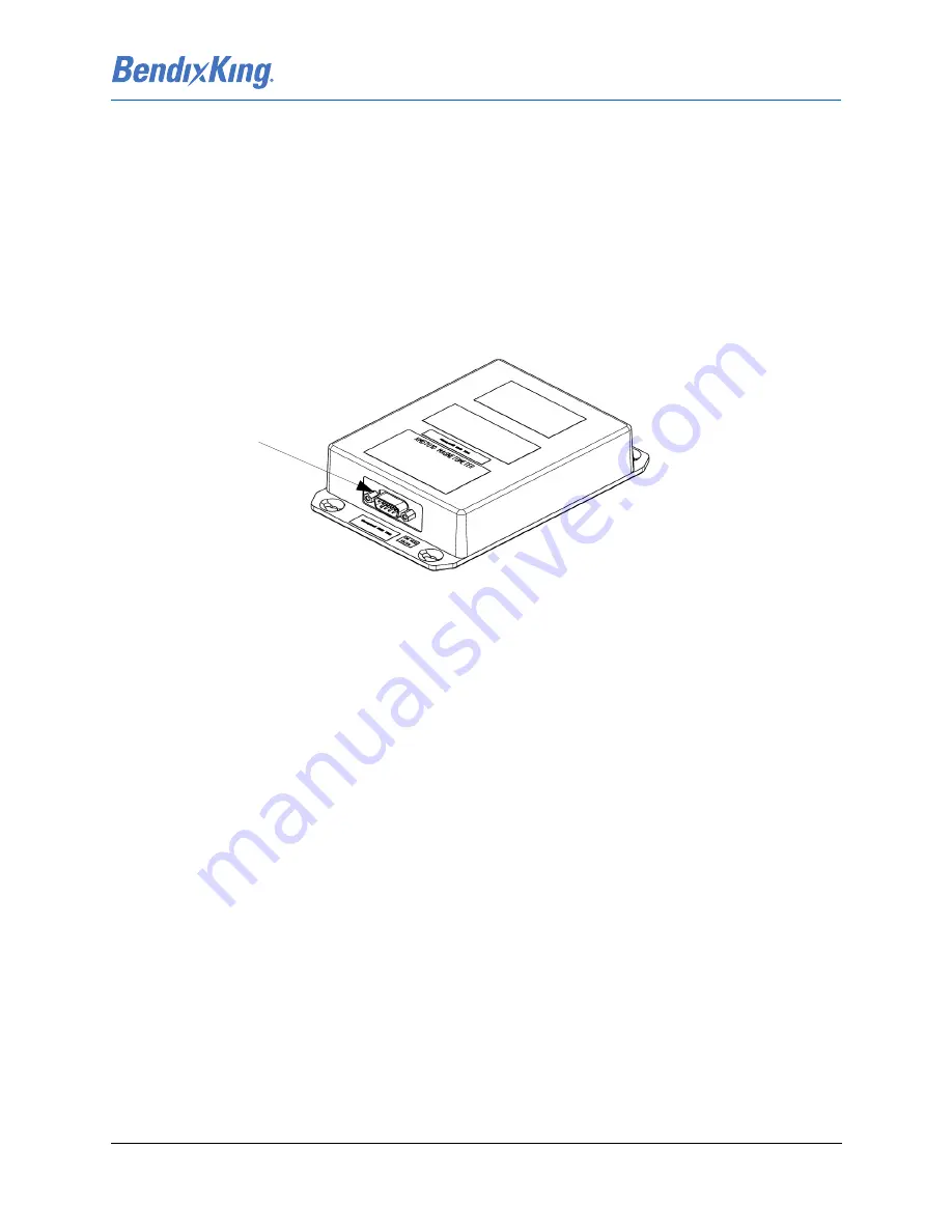
The KMG 7010 Magnetometer (Figure 4-16) must be installed in an area that is free of magnetic
disturbances from either ferrous materials or locally generated magnetic fields.
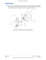
Figure 4-16 KMG 7010 Magnetometer
The KMG 7010 supports variability related to its orientation. The connector of the KMG 7010 can be
oriented towards the airplane nose or tail, towards left or right wing or can be oriented down.
The KMG 7010 can be rotated to 4 orientations around the axis which is oriented towards the
magnetometer connector.
The only restriction is that, once the KMG 7010 is installed, the KMG 7010 pitch and roll offsets should be
within ±5 degrees from the airplane pitch and roll. The total count of acceptable installation orientations
is 24, see Table 6-7 KMG 7010/MD32 Installation Orientation Options.
4.6.1 KMG 7010 Installation Procedures
(1) Ensure all wiring and power checks have been completed per Section 6.1.
(2) Ensure all power is removed from airplane.
(3) See Table 6-7 KMG 7010/MD32 Installation Orientation Options for mounting options and Figure
A-8 KMG 7010 Outline and Mounting Drawing (Sheet 1 of 2) for unit dimensions and center of
gravity information.
(4) Fabricate a mounting adapter plate (if needed).
(5) Prepare mounting hole locations as bonding points such that the bonding resistance conforms to
the guidelines listed in Section 3.10 Electrical Bonding Considerations. Ensure the installation
provides a 10.0 milliohm max impedance bond from the harness backshell to the airplane ground.
(6) Apply conversion coating material conforming to MIL-C-81706 per AC 43-13-1B, to exposed metal
surfaces.
(7) Install mounting adapter plate (as applicable).
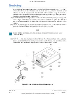
(8) Using the KMG 7010 Installation Kit, mount the KMG 7010 with the four #10-32 mounting screws,
P1

