89000109-002
xVue Touch Installation Manual
Rev 2
Page 4-15
© Honeywell International Inc. Do not copy without express permission of Honeywell.
For Use in Non-Certified Aircraft
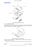
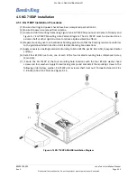
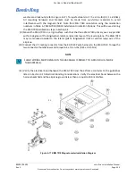
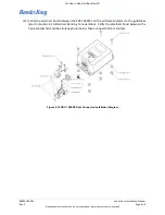
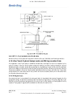
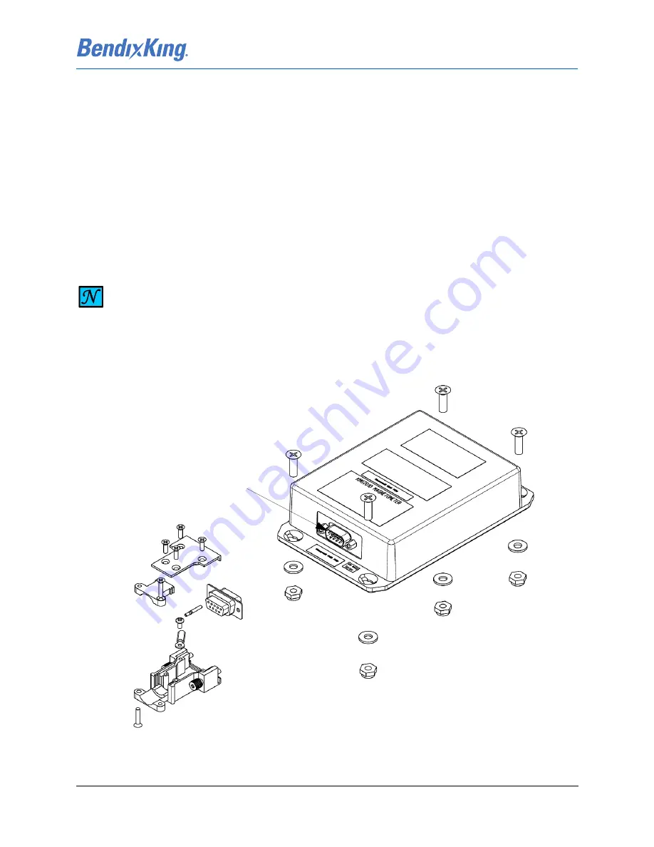
washers and lock nuts (refer to Figure 4-17). Torque fasteners to 27.5 ± 2.5 in-lbs (3.11 ± .28 Nm).
All mounting hardware and brackets must be made from non-ferrous materials to avoid
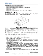
interference with the magnetic field. Note the KMG 7010 orientation using the orientation
numbers in Table 6-7 KMG 7010/MD32 Installation Orientation Options. This will be used during
the KMG 7010 calibration steps in
(9) Mount the KMG 7010 on a rigid surface such that the three KMG 7010 primary axes are parallel
within 5 degrees of the longitudinal, lateral, and vertical axes of the level airplane. The KMG 7010
may be mounted parallel to the lateral (pitch), longitudinal (roll) or vertical (yaw) axis of the
airplane.
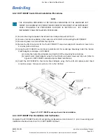
(10) Connect the J71 mating connector from the KG 71EXP wire harness to the KMG 7010. Torque the
two connector thumbscrews and torque to 4 ± 0.4 in-lbs (0.45 ± 0.05 Nm).
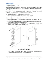
(11) Verify the electrical bond between the KMG 7010 and the airframe conforms to the guidelines
listed in Section 3.10 Electrical Bonding Considerations. Verify the electrical bond between the
harness backshell and the airplane ground is less than or equal to 10.0 milliohms.
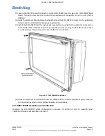
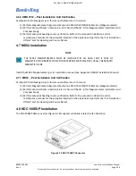
Figure 4-17 KMG 7010 Magnetometer Installation Diagram
NOTE
SHIELD WIRING MUST REMAIN IN THE BACKSHELL (CONNECT TO GROUND LUG INSIDE
THE BACKSHELL).
P1

