89000109-002
xVue Touch Installation Manual
Rev 2
Page 4-19
© Honeywell International Inc. Do not copy without express permission of Honeywell.
For Use in Non-Certified Aircraft
4.8.2 KDC 100EXP – Post Installation Unit Verification
Accomplish the following steps in this manual before return to service:
(1) Perform Magnetometer Alignment (Section 6.4 KMG 7010/MD32 Calibration (Magnetometer)).
(2) Perform Ground Checks in Section 3.6.8.3.2 Ground Checks - After Magnetometer Installation and
(3) Perform autopilot heading course verification. Refer to the autopilot installation and/or
maintenance manual for the autopilot installed in the airplane and perform the “Set Installation
Offsets” test for Heading and Course Datum.
4.9 KTP 73 Installation
4.9.1 KTP 73 Installation Procedures
(1) Ensure all power is removed from airplane.
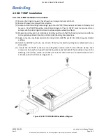
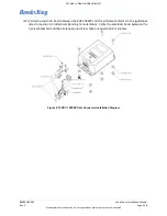
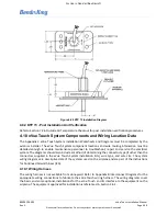
(2) At the selected location for the KTP 73 locate and drill four mounting holes and center hole in
airplane skin shown in Figure A-14 KTP 73 Mounting Hole Pattern (also refer to the 1:1 scale
drawing - available for download on the BendixKing Website - Dealer Portal). See Figure 4-20 for
additional reference information.
(3) A reinforcement doubler is required with the KTP 73 installation if the aircraft skin does not have
unreinforced holes of 0.20 inch diameter or larger in the nearby area. A generic doubler and its
installation is shown in Figure A-15 for use with aircraft skins from 0.016 to 0.032 inch thickness.
The number rivets can be increased and shape of the doubler modified to suit the particular
installation. For thicker skins a separate approval is required. Do not install the KTP 73 in skin
thinner than 0.016 inch.
(4) Prepare airplane skin mounting hole locations as bonding points such that a bonding resistance of
no more than 2.5 milliohms is achieved as measured between the mounting block and airplane
skin.
(5) Apply conversion coating material conforming to MIL-C-81706 per AC 43-13-1B, to exposed metal
surfaces.
(6) Install four #6-32 stainless steel mounting screws through the outside of the airplane skin into
mounting block using thread-locking compound. Torque fasteners to a minimum of 10 ± 1 in- lbs.
(1.13 ± .11 NM). Once installed, screws must have a minimum of three full screw threads exposed
above the mounting block.
(7) Apply sealer around the sensor block, doubler plate (if installed), and airplane skin penetration to
prevent the ingress of moisture to the airframe.
(8) Splice and shield KTP 73 lead wires into airplane wiring harness. Connections for the lead wires
and shield to be accomplished using heat-shrink butt-splices. Additional lead wire may be added
using M27500-22TE3T14 wire or similar. Refer to Table 5-4 KG 71EXP J71 Pin Descriptions
(Viewed from LRU) for KTP 73 wiring to the KG71EXP ADAHRS and refer to Table 5-10 KTP 73 Wire
Descriptions.
(9) Extend shield/overbraid and bond to the KG 71EXP.
(10) Verify the electrical bond between the mounting block and the airplane skin conforms to the

