89000109-002
xVue Touch Installation Manual
Rev 2
Page 6-50
© Honeywell International Inc. Do not copy without express permission of Honeywell.
For Use in Non-Certified Aircraft
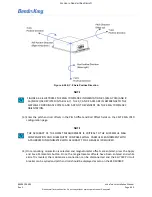
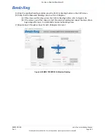
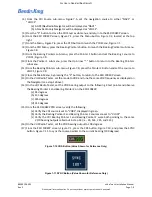
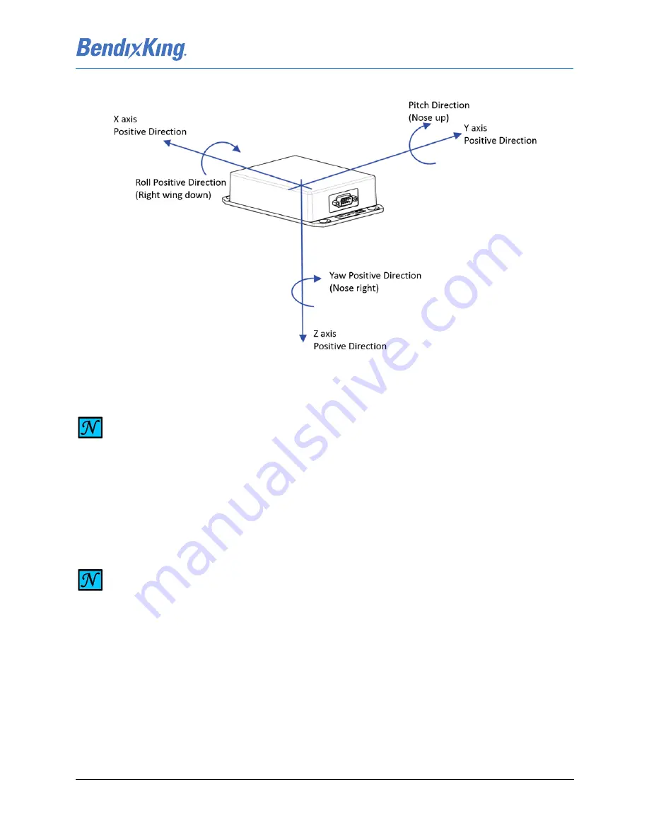
Figure 6-54 X, Y, Z Axis Positive Direction
(3) Enter the pitch and roll offsets in the Pitch Offset and Roll Offset fields on the CMT KMG 7010
configuration page.
(4) Once mounting orientation is selected and magnetometer offsets are entered, press the Apply
and Save Parameters button. Once the magnetometer offsets have been entered and while
aircraft is leveled, the maintenance connection can be disconnected and the KG 71EXP circuit
breaker can be cycled and pitch and roll should be displayed as zero on the KSD 100EXP.
NOTE
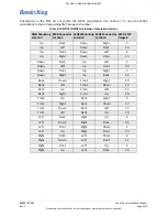
FIGURE 6-54 ILLUSTRATES THE KMG 7010/MD32 IN ORIENTATION # 5 (KMG 7010) AND #
16 (MD32) (AS DEPICTED IN TABLE 6-7). THE X,Y, AND Z AXES ARE IN REFERENCE TO THE
AIRPLANE COORDINATE SYSTEM AND ARE NOT DEPENDENT ON THE KMG 7010/MD32
ORIENTATION.
NOTE
THE ACCURACY OF THE OFFSET MEASUREMENT IS CRITICAL TO THE SUCCESSFUL MAG
COMPENSATION AND SUBSEQUENT COMPASS SWING. CAREFUL MEASUREMENT WITH
A CALIBRATED INCLINOMETER WITH ACCURACY TO 0.1 DEGREES IS REQUIRED.

