89000109-002
xVue Touch Installation Manual
Rev 2
Page 7-8
© Honeywell International Inc. Do not copy without express permission of Honeywell.
For Use in Non-Certified Aircraft
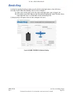
(c) Verify the CDI course deviation (left/right) matches the GPS Navigators CDI deviation.
(d) Verify the Bearing Pointer 1 and Bearing Pointer 2 sources are set to “GPS1”.
(e) Verify the CDI Bearing Pointer 1 and Bearing Pointer 2 are both pointing in the direction of
the Navigators Direct-To waypoint, relative to the airplane position.
(16) On the Navigator, clear the existing Flight Plan/Direct-To.
(17) From the KSD 100EXP PFD screen, verify the following:
(a) Verify the CDI source is set to “GPS1”, displayed in magenta.
(b) Verify the CDI course deviation (left/right) is removed from the PFD CDI.
(c) Verify the Bearing Pointer 1 and Bearing Pointer 2 sources are set to “GPS1”.
(d) Verify the CDI Bearing Pointer 1 and Bearing Pointer 2 are both removed from the PFD
CDI.
(18) On the Navigator, enter a new flight plan with the TO waypoint being an OBS defined course.
(19) On the KCP 100EXP, press the CRS knob to sync the CDI CRS numeric value and CDI course pointer
to current GPS1 bearing.
(20) From the KSD 100EXP PFD screen, verify the following:
(a) Verify the CDI source is set to “GPS1”, displayed in magenta.
(b) Verify the CDI course deviation is centered with no left/right deflection.
(c) Verify the CDI CRS numeric value and CDI course pointer matches the Bearing Pointer 1
and Bearing Pointer 2.
(21) On the KCP 100EXP, rotate the CRS knob counterclockwise such that the CDI course pointer is to
the left of the GPS1 bearing.
(22) From the KSD 100EXP PFD screen, verify the following:
(a) Verify the CDI source is set to “GPS1”, displayed in magenta.
(b) Verify the CDI course deviation is deflected to the right (towards the bearing pointers).
(23) On the KCP 100EXP, rotate the CRS knob clockwise such that the CDI course pointer is to the right
of the GPS1 bearing.
(24) From the KSD 100EXP PFD screen, verify the following:
(a) Verify the CDI source is set to “GPS1”, displayed in magenta.
(b) Verify the CDI course deviation is deflected to the left (towards the bearing pointers).
(25) If a second GPS Navigator is installed in the airplane, repeat the above steps for “NAV2” or
“GPS2”.
(a) A second GPS/Nav Radio Navigator will be displayed as “NAV2”.
(b) A second GPS only Navigator will be displayed as “GPS2”.
7.2.8 NAV Receiver
A VHF Radio Navigation Tester (for example, a Nav 401L for testing and calibration of, VOR, LOC, and G/S)
is required for the following procedure. To comply with 14 CFR Part 91.171 the maximum permissible
indicated bearing error is ± 4 degrees for IFR operations.
(1) On the Navigator, tune/activate the VHF radio to a valid VOR frequency.
(2) On the Navigator, set the CDI switch to VLOC.
(a) A GPS/Nav Radio Navigator CDI switch can be set to either GPS or VLOC.
(b) A Nav Radio Navigator will not have a CDI switch, and this step 2 can be ignored.
(3) From the KSD 100EXP screen, press the CDI button located at the bottom of the PFD screen,

