89000109-002
xVue Touch Installation Manual
Rev 2
Page 7-9
© Honeywell International Inc. Do not copy without express permission of Honeywell.
For Use in Non-Certified Aircraft
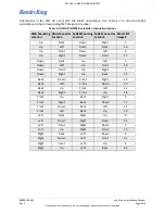
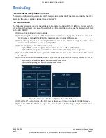
(4) From the CDI Source sub-menu, Figure 7-5, set the navigation source to either “NAV1” or
“VLOC1”.
(a) A GPS/Nav Radio Navigator will be displayed as “NAV1”.
(b) A Nav Radio only Navigator will be displayed as “VLOC1”.
(5) Press the “X” button to close the CDI Source sub-menu and return to the KSD 100EXP screen.
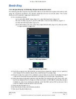
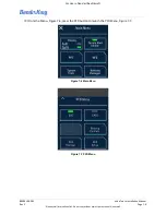
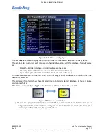
(6) From the KSD 100EXP screen, Figure 7-1, press the Menu button, Figure 7-2, located at the top
right.
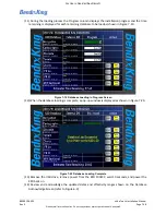
(7) From the Menu, Figure 7-6, press the PFD button to launch the PFD Menu, Figure 7-7.
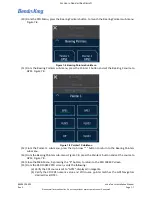
(8) From the PFD Menu, press the Bearing Pointers button, to launch the Bearing Pointers sub-menu,
(9) From the Bearing Pointers sub-menu, press the Pointer 1 button and set the Bearing 1 source to
(10) From the Pointer 1 sub-menu, press the Up Arrow “^” button to return to the Bearing Pointers
sub-menu.
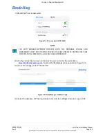
(11) From the Bearing Pointers sub-menu, Figure 7-8, press the Pointer 2 button and set the source to
(12) Close the Main Menu, by pressing the “X” button, to return to the KSD 100EXP screen.
(13) On the VHF Radio Tester, set the mode to VOR and tune the same VOR frequency as displayed on
the Navigator (see step 1 above).
(14) On the VHF Radio Tester, set the VOR bearing output to the following 4 test points and observe
the Bearing Pointer 1 and Bearing Pointer 2 on the KSD 100EXP:
(a) 45 degrees
(b) 135 degrees
(c) 225 degrees
(d) 315 degrees
(15) From the KSD 100EXP PFD screen, verify the following:
(a) Verify the CDI source is set to “VOR1”, displayed in green.
(b) Verify the Bearing Pointer 1 and Bearing Pointer 2 sources are set to “VLOC1”.
(c) Verify the CDI Bearing Pointer 1 and Bearing Pointer 2 were both pointing to the same
VOR bearing outputs called out in step 14 (i.e., 45, 135, 225, and 315).
(16) On the VHF Radio Tester, set the VOR bearing output to 100 degrees.
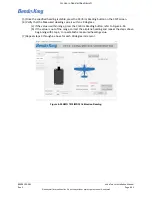
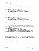
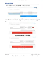
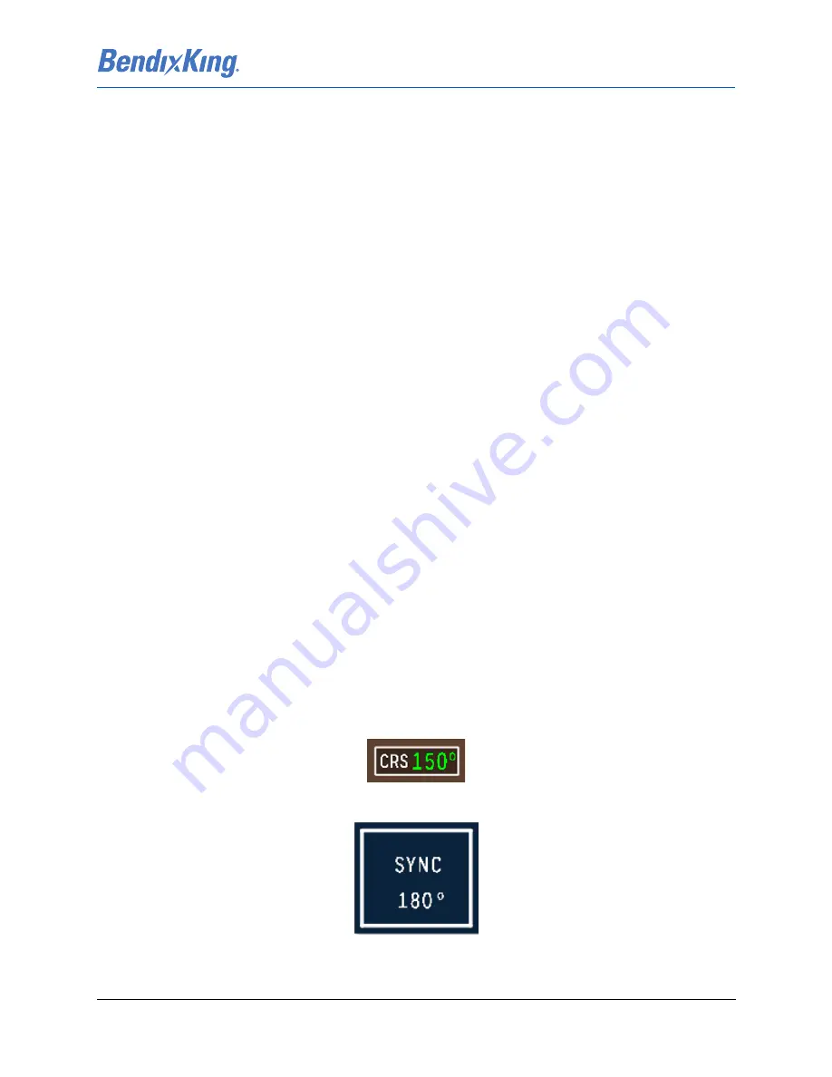
(17) From the KSD 100EXP screen, Figure 7-1, press the CRS button, Figure 7-10, and press the SYNC
button, Figure 7-11, to sync the course pointer to the current bearing (100 degrees).
Figure 7-10 CRS Button (Value Shown for Reference Only)
Figure 7-11 SYNC Button (Value Shown for Reference Only)

