27
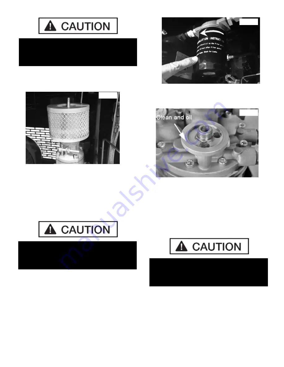
3. Check the condition of intake filter, either blow it clean
with compressed air or replace if necessary.
(See Fig. 12.7)
4. Inspect the inside of the plastic Intake Air Filter
housing and remove hose clamp and clean if necessary.
5. Reinstall the Intake Air Filter Housing and new Filter
and Twist the Intake Air Filter Cover clockwise to tighten.
OIL FILTER REPLACEMENT PROCEDURE
The Oil Separation Filter is a spin-on style of filter like that
of a typical automotive oil filter making for easy replace
-
ment.
1. Remove the Access panel on the left side / Oil
Separator Side of the Compressor.
(See Section 8; Fig. 8.3)
2. Using an Oil Filter wrench if necessary, unscrew the
Oil Filter counter clock wise. (See Fig. 12.8 )
3. Clean the threads and seat and then apply a light
layer of clean oil to the face of the Oil Filter seat.
(See Fig. 12.9)
4. Screw the new Oil Filter on clockwise and hand
tighten only.
AIR OIL SEPARATION FILTER
REPLACEMENT PROCEDURE
1. Remove the Access panel on the Rear Side of the
Compressor.
NOTE:
The Oil Separation Tank needs to be unbolted and
tilted to provide adequate clearance for removal of
the Air Oil Separator Filter.
2. Unbolt the Oil Separation Tank mounting bolts.
(See Fig. 12.10 )
Fig. 12.9
ENSURE THAT NO FOREIGN OBJECTS OR
DEBRIS FALLS INTO THE INTAKE AREA DURING
MAINTENANCE PROCEDURES.
PERFORM THE LOCKOUT TAG OUT AND
DEPRESSURIZATION PROCEDURES AS
OUTLINED IN SECTION 12.1.
PERFORM THE LOCKOUT TAG OUT AND
DEPRESSURIZATION PROCEDURES AS
OUTLINED IN SECTION 12.1.
Fig. 12.7
Fig. 12.8
Summary of Contents for RS7580H603
Page 34: ...34 Frequent ...
Page 35: ...35 ...
Page 36: ...36 RS7580H603 SCREW COMPRESSOR PARTS LIST ...
Page 37: ...37 RS7580H603 SCREW COMPRESSOR PARTS LIST ...
Page 38: ...38 RS7580H603 SCREW COMPRESSOR PARTS LIST ...
Page 40: ...40 RS7580H603 SCREW COMPRESSOR PARTS LIST ...
Page 41: ...41 RS7580H603 SCREW COMPRESSOR PARTS LIST ...
Page 42: ...42 RS7580H603 COMPRESSOR ELECTRIC DIAGRAM ...
Page 43: ...43 RS7580H603 COMPRESSOR ELECTRIC DIAGRAM ...
Page 44: ...44 RS7580H603 COMPRESSOR ELECTRIC DIAGRAM ...
Page 45: ...45 ...
Page 48: ......


