


14
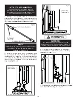
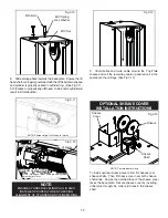
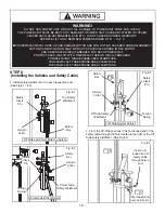
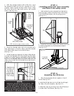
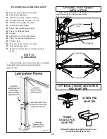
5. If shimming is required, insert the shims as necessary
under the base plate so that when the anchor bolts are
tightened, the posts will be plumb. (See Fig. 5.3)
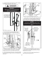
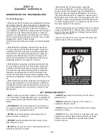
6. If installing the optional foot guards, place foot guards
on left and right side as shown. (See Fig 5.4)
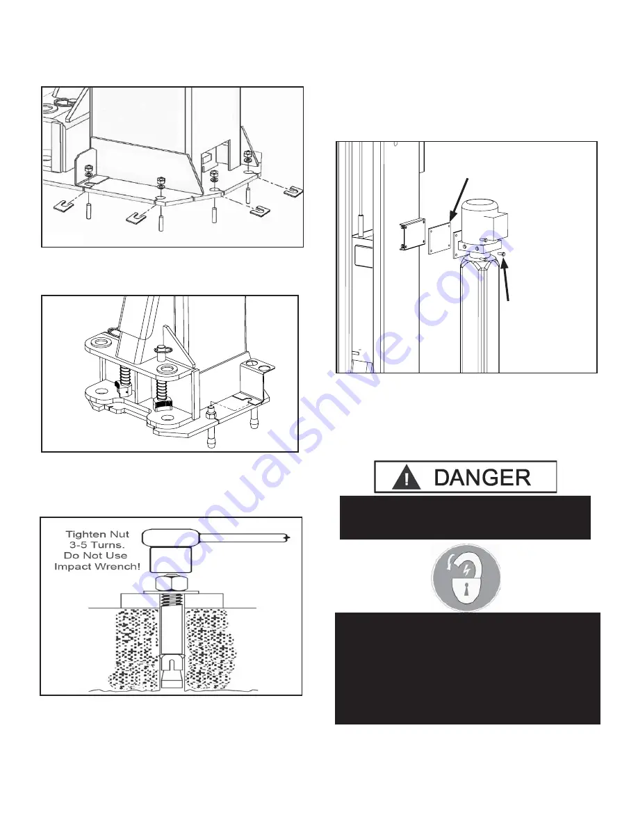
7. With the foot guards, shims and anchor bolts in place,
tighten by securing the nut to the base then turning 3-5 full
turns clockwise (90 ft-lbs.).
DO NOT
use an impact wrench
for this procedure. (See Fig. 5.5)
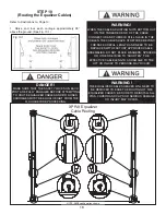
STEP 6
(Installing the OFF SIDE post)
1. Position the OFF SIDE post at the designated chalk
locations and secure post to fl oor following the same proce-
dures as outlined in STEP 5; Paragraphs 1-6.
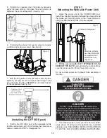
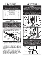
STEP 7
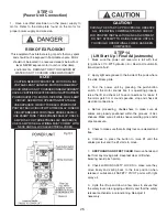
(Mounting the Hydraulic Power Unit)
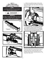
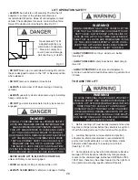
1. Attach the power unit to the POWER SIDE post.
Install the vibration dampener between the power unit and
the power unit mounting plate on the Power Side post,
using four M8 hex head bolts and nuts supplied.
(See Fig 7.1)
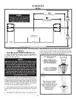
2. Fill the reservoir with 10 WT. HYDRAULIC OIL OR
DEXRON TYPE III ATF,
approximately four gallons
.
Make
sure the funnel used to fi ll the Power Unit is clean.
Do not connect power unit hydraulic hose assembly at
this time.
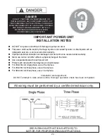
3. The standard power unit for your lift is 220 volt, 60HZ,
single phase. All wiring must be performed by a certifi ed
electrician only. SEE WIRING INSTRUCTIONS AFFIXED
TO MOTOR FOR PROPER WIRING INSTRUCTIONS.
Fig 5.3
Fig 5.4
Fig 5.5
Fig 7.1.
Vibration Dampener
M8 x1.25 x 35mm
hex head bolts, M8
fl at washers and
M8 Nylock nuts
(Qty 4 ea)
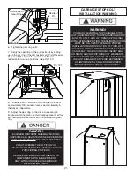
DANGER !
ALL WIRING MUST BE PERFORMED
BY A LICENSED ELECTRICIAN.
DANGER!
DO NOT PERFORM ANY MAINTENANCE OR
INSTALLATION OF ANY COMPONENTS WITHOUT
FIRST ENSURING THAT ELECTRICAL POWER HAS
BEEN DISCONNECTED AT THE SOURCE OR PANEL
AND CANNOT BE RE-ENERGIZED UNTIL ALL
MAINTENANCE AND/OR INSTALLATION
PROCEDURES ARE COMPLETED.


