16
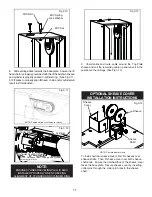
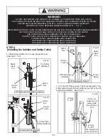
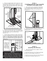
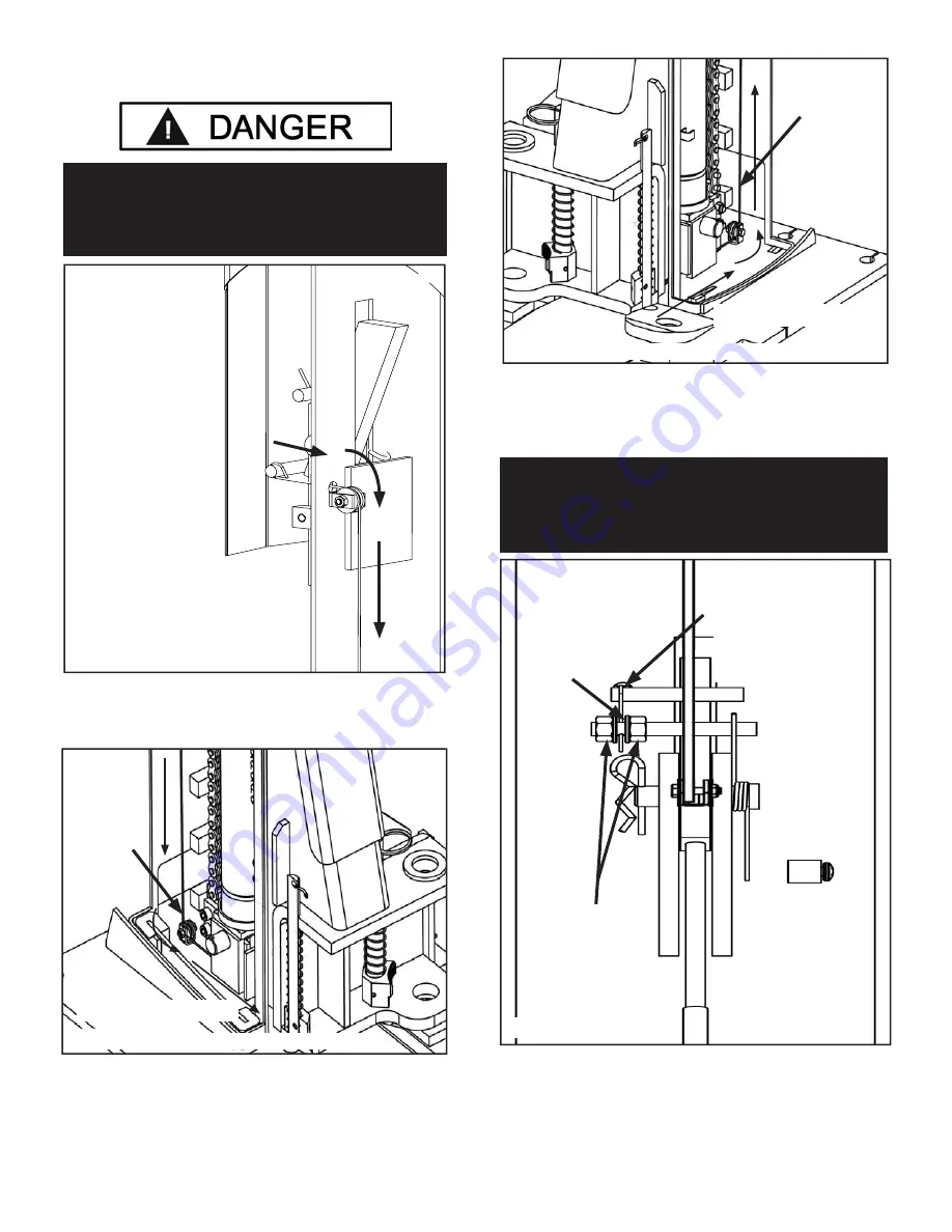
3. Route the cable over the sheave and route it towards
the baseplate safety sheave. (See Fig 8.5)
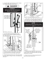
4. Route the cable through the baseplate’s safety
sheave(s) and across the fl oor towards the Power Side
post. (See Fig 8.6 - 8.7)
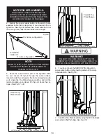
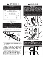
5. Route the cable the same way as on the Off Side
going up the post and over the safety cable sheave.
6. Route the cable over the top pin on the safety handle.
Insert the cable end through the hole on the threaded pin.
(See Fig 8.7)
7. Pull the slack out the safety cable and keep tension
on the cable as nuts are being tightened. Tighten jam
nuts on either side of the cable keeping the cable cen-
tered to the hole to secure it into place. (See Fig 8.8)
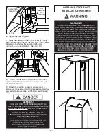
8. Operate the Power Side safety handle, check for
proper operation of both safety assemblies and adjust
cable tension as required.
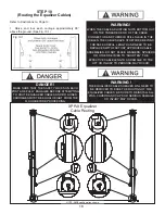
9. Raise and lock each carriage approximately 28”
above the ground. (See Fig. 8.9)
DANGER !
ENSURE THAT BOTH THE POWER SIDE &
OFF SIDE SAFETIES ENGAGE PROPERLY
PRIOR TO LIFT OPERATION.
Fig 8.5
Route safety cable
over Off Side safety
sheave and down
towards base plate
NOTE: Post cut away for clarity
Fig 8.5
Safety
Cable
NOTE: Post and carriage cut away for clarity
To Power Side Post
Fig 8.6
From Off Side Post
Fig 8.6
Safety
Cable
NOTE: Post and carriage cut away for clarity
Fig 8.7
NOTE:
MAKE SURE TO KEEP THE SAFETY CABLE
CENTERED WHEN TIGHTENING JAM NUTS ON
SAFETY.
Fig 8.8
Route safety
cable over the top
pin of the Power
Side Safety
Weldment
Route safety
cable the
hole in the
threaded pin
Tighten jam
nuts ensuring
safety cable is
centered in hole


