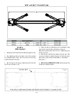
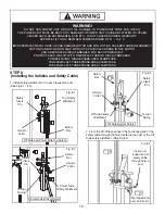


21
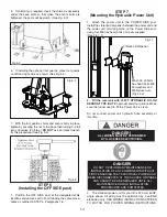
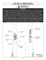
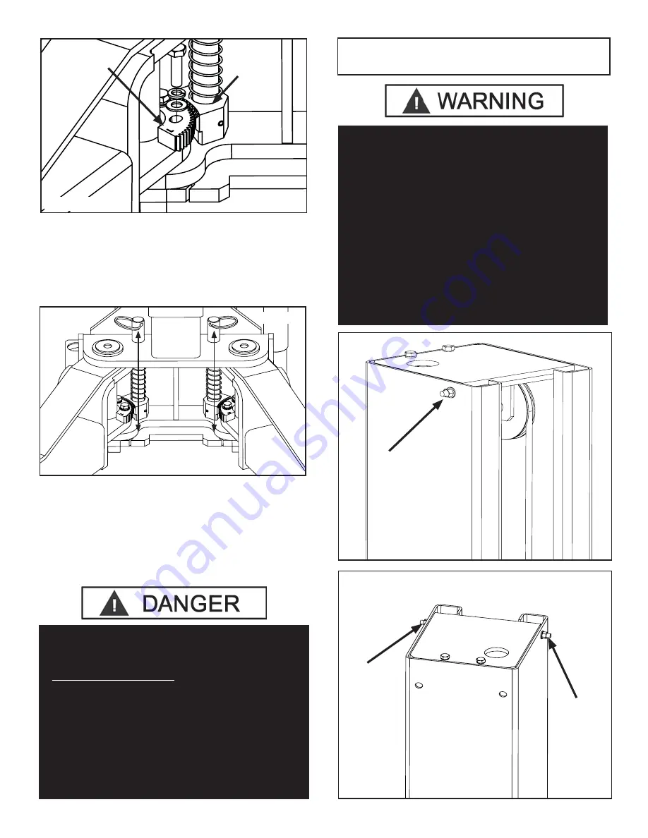
6. Tighten the gear ring bolts.
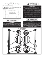
7.
Verify the operation of the arm restraints by pulling
up on the key ring of the arm restraint pin. Pivot the arms
back and forth and test the operation of the arm
restraint pin in various positions. (See Fig. 12.7)
8. Ensure that the arms do not move when a force of
approximately 100 pounds or less is applied laterally to
the fully extended arms.
9. Adjust the gear ring on the arm as necessary to
ensure smooth operation and solid engagement of all four
arm restraint pin assemblies with the arm restraint gear
ring.
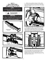
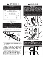
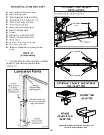
Fig. 12.6
Arm Restraint
Gear Ring
Arm
Restraint
Pin
Assembly
Fig. 12.7
DANGER!
EACH ARM RESTRAINT ASSEMBLY MUST BE
INSPECTED AND ADJUSTED AS NEEDED BEFORE
EACH AND EVERY TIME THE LIFT IS OPERATED.
DO NOT OPERATE THE LIFT IF ANY OF
THE FOUR ARM RESTRAINT SYSTEMS ARE NOT
FUNCTIONING PROPERLY.
REPLACE ANY BROKEN COMPONENTS OR
COMPONENTS WITH BROKEN TEETH
ONLY WITH AUTHORIZED OR APPROVED
REPLACEMENT PARTS.
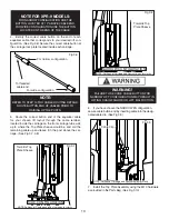
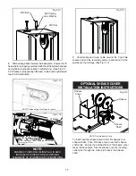
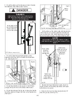
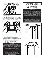
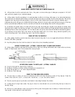
WARNING!
YOU MUST RE-INSTALL TOP CARRIAGE-STOP
BOLT (SHOWN BELOW). TIGHTEN CARRIAGE-STOP
BOLT TO 2-3 FT.-LBS. OF TORQUE UPON FINAL
INSTALLATION INSPECTION. THESE INSTRUCTIONS
MUST BE FOLLOWED TO ENSURE PROPER
INSTALLATION AND OPERATION OF YOUR LIFT.
FAILURE TO COMPLY WITH THESE INSTRUCTIONS
CAN RESULT IN SERIOUS BODILY INJURY AND/
OR DEATH AND/OR VOID PRODUCT WARRANTY.
MANUFACTURER WILL ASSUME NO LIABILITY FOR
LOSS OR DAMAGE OF ANY KIND, EXPRESSED
OR IMPLIED RESULTING FROM IMPROPER
INSTALLATION OR USE OF THIS PRODUCT.
CARRIAGE STOP BOLT
INSTALLATION WARNING


