
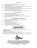
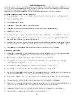


38
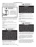
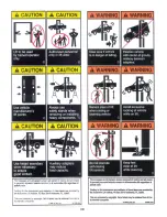
DO NOT
leave the controls while the lift is still in motion.
DO NOT
stand directly in front of the vehicle or in the bay when vehicle is being loaded or driven into position.
DO NOT
go near vehicle or attempt to work on the vehicle when being raised or lowered.
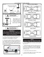
REMAIN CLEAR
of lift when raising or lowering vehicle.
DO NOT
rock the vehicle while on the lift or remove any heavy component from vehicle that may cause excessive
weight shift.
DO NOT
lower the vehicle until people, materials, and tools are clear
ALWAYS ENSURE
that the safeties are engaged and lowered on to the safeties before any attempt is made to
work on or near vehicle.
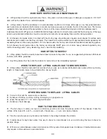
Some vehicle maintenance and repair activities may cause the vehicle to shift. Follow the manufacturer’s guidelines
when performing these operations. The use of jack stands or alternate lift points may be required when completing
some repairs.
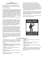
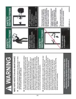
READ AND UNDERSTAND
all safety warning procedures before operating lift.
KEEP HANDS AND FEET CLEAR
. Remove hands and feet from any moving parts. Keep feet clear of lift when lowering.
Avoid pinch points.
ONLY TRAINED OPERATORS
should operate this lift. All non-trained personnel should be kept away from work area.
Never
let
non-trained personnel come in contact with, or operate lift.
USE LIFT CORRECTLY
. Use lift in the proper manner. Never use lifting adapters other than what is approved by the
manufacturer.
DO NOT
override self-closing lift controls.
CLEAR AREA
if vehicle is on danger of falling.
STAY ALERT
. Watch what you are doing. Use common sense. Be aware.
CHECK FOR DAMAGED PARTS
. Check for alignment of moving parts, breakage of parts or any condition that may
affect its operation. Do not use lift if any component is broken or damaged.
NEVER
remove safety related components from the lift. Do not use lift if safety related components are damaged or
missing.
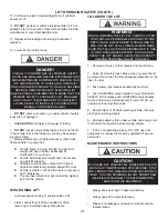
When the lift is being lowered, make sure everyone is standing at least six feet away.
Be sure there are no jacks, tools, equipment, left under the lift before lowering.
Always lower the vehicle down slowly and smoothly.


