background image

6

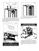
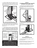
1. Carefully remove the crating and packing 
materials. CAUTION! Be careful when cutting steel 
banding material as items may become loose and fall 
causing personal harm or injury.

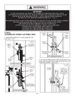
2. Check the voltage, phase, and proper amperage 
requirements for the motor shown on the motor plate. 
Electrical work should be performed only by a certifi ed 
electrician.

IMPORTANT SAFETY INSTRUCTIONS

Read  these  safety  instructions  entirely.  Do  not  attempt  to  install  this  lift  if  you  have  never  been  trained                         

on basic automotive lift installation procedures. Never attempt to lift components without proper lifting tools such as                       

forklift or cranes. Stay clear of any moving parts that may fall and cause injury. When using your garage equipment, 

basic safety precautions should always be followed, including the following:

INTRODUCTION

1.  Read and understand all instructions and all safety warn-
ings before operating lift.
2.   Care must be taken as burns can occur from touching 
hot parts.
3.   Do not operate equipment with a damaged cord or if the 
equipment has been dropped or damaged until it has been 
examined by a qualifi ed service person.
4.   Do not let a cord hang over the edge of the table, bench, 
or counter or come in contact with hot manifolds or moving 
fan blades.
5.   If an extension cord is necessary, a cord with a current 
rating equal to or more than that of the equipment should be 
used. Cords rated for less current than the equipment may 
overheat. Care should be taken to arrange the cord so that it 
will not be tripped over or pulled.
6.   Always unplug equipment from electrical outlet when not 
in use. Never use the cord to pull the plug from the outlet. 
Grasp plug and pull to disconnect.
7.   Let equipment cool completely before putting away. Loop 
cord loosely around equipment when storing.
8.   To reduce the risk of fi re, do not operate equipment in the 
vicinity of open containers of fl ammable liquids (gasoline).
9.   Adequate ventilation should be provided when working 
on operating internal combustion engines.
10.  Keep hair, loose clothing, fi ngers, and all parts of body 
away from moving parts. Keep feet clear of lift when lowering.  
Avoid pinch points.
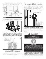
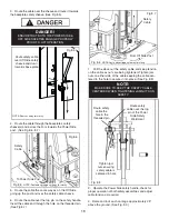
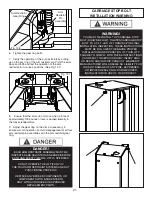
11.  DANGER! To reduce the risk of elec-
tric shock, do not use on wet surfaces or 
expose to rain. The power unit used on 
this lift contains high voltage. Disconnect 
power at the receptacle or at the circuit 
breaker switch before performing any elec-
trical repairs. Secure plug so that it cannot 
be accidentally plugged in during service. or 
mark circuit breaker switch so that it cannot 
be accidentally switched on during service.
12.  Use only as described in this manual.  
Use only manufacturer’s recommended attachments.

13. ALWAYS WEAR SAFETY GLASSES. Everyday eye-
glasses only have impact resistant lenses, they are not safety 
glasses.
14. Consider work environment. Keep work area clean. 


Cluttered work areas invite injuries. Keep areas well lit.
15. Guard against electric shock. This lift must be grounded 
while in use to protect operator from electric schock. Never 
connect the green power cord wire to a live terminal. This is 
for ground only.
16. Only trained operators should operate this lift. All non-
trained personnel should be kept away from the work area. 
Never let non-trained personnel come in contact with, or 
operate lift.
17. DO NOT override self-closing lift controls.
18. Clear area if vehicle is in danger of falling.
19. ALWAYS make sure the safeties are engaged before 
attempting to work on or near a vehcile.
21. WARNING! RISK OF EXPLOSION. This 
equipment has internal arcing or sparking 
parts which should not be exposed to fl am-
mable vapors. This machine should not be 
located in a recessed area or below fl oor 
level.
22. MAINTAIN WITH CARE. Keep lift clean for better and 
safer performance. Follow manual for proper lubrication and 
maintenance instructions. Keep control handles and/or but-
tons dry, clean and free from grease and oil.
23. Check for damaged parts.  Check for alignment of mov-
ing parts, breakage of parts or any condition that may affect 
operation of lift. Do not use lift if any component is broken or 
damaged.
24. NEVER remove safety related components from the lift. 
Do not use lift if safety related components are missing or 
damaged.
23. STAY ALERT. Use common sense and watch what you 
are doing.  Remember, SAFETY FIRST.

SAVE THESE INSTRUCTIONS

Summary of Contents for XPR-9

Page 1: ...on on the part of the operator DO NOT operate or repair this equipment without reading this manual and the important safety instructions shown inside Keep this operation manual near the lift at all times Make sure that ALL USERS read and understand this manual 1645 Lemonwood Dr Santa Paula CA 93060 USA Toll Free 1 800 253 2363 Tel 1 805 933 9970 Fax 1 805 933 9160 wwwbendpak com 9 000 POUND CAPACI...

Page 2: ...the warranty period those parts returned to the factory freight prepaid which prove upon inspection to be defective BendPak Inc will pay labor costs for the first 12 months only on parts returned as previously described The warranty does not extend to defects caused by ordinary wear abuse misuse negligence shipping damage improper installation voltage or lack of required maintenance damages result...

Page 3: ...ns Follow all installation and operation instructions Make sure installation conforms to all applicable Local State and Federal Codes Rules and Regulations such as State and Federal OSHA Regulations and Electrical Codes Carefully check the lift for correct initial function Read and follow the safety instructions Keep them readily available for machine operators Make certain all operators are prope...

Page 4: ...Side Post 14 Step 7 Mounting The Hydraulic Power Unit 14 15 Step 8 Installing the Safeties and Safety Cable 15 17 Step 9 Installing Hydraulic Lines 17 Step 10 Routing the Equalizer Cables 18 19 Step 11 Installing Power Unit Hose Assembly and Power Side Safety Cover 19 Step 12 Installing the Lift Arms 19 21 Carriage Stop Bolt Installation Warning 21 Leveling Instructions 22 Safety Label Placement G...

Page 5: ...or bystander or damage to property or lift Failure to follow Danger Warning and Caution instruc tions may lead to serious personal injury or death to operator or bystander or damage to property Please read the entire manual prior to installation Do not operate this machine until you have read and have understood all of the Danger Warning and Caution alerts in this manual For additional copies or f...

Page 6: ...of body away from moving parts Keep feet clear of lift when lowering Avoid pinch points 11 DANGER To reduce the risk of elec tric shock do not use on wet surfaces or expose to rain The power unit used on this lift contains high voltage Disconnect power at the receptacle or at the circuit breaker switch before performing any elec trical repairs Secure plug so that it cannot be accidentally plugged ...

Page 7: ... this lift outdoors CONCRETE SPECIFICATIONS LIFT MODEL CONCRETE REQUIREMENTS XPR 9 4 Min Thickness 3 000 PSI DANGER ALL MODELS MUST BE INSTALLED ON 3000 PSI CONCRETE ONLY CONFORMING TO THE MINIMUM REQUIREMENTS SHOWN ABOVE NEW CONCRETE MUST BE ADEQUATELY CURED FOR A MINIMUM OF 28 DAYS IMPORTANT NOTICE THESE INSTRUCTIONS MUST BE FOLLOWED TO INSURE PROPER INSTALLATION AND OPERATION OF YOUR LIFT FAILU...

Page 8: ...t or some other heavy lifting device PARTS INVENTORY Be sure to take a complete inventory of parts prior to beginning installation Description Qty Floorplate 1 Front Arm Assembly 2 Rear Arm Assembly 2 Off Side Post with Carriage Assembly 1 Power Side Post with Carriage Assembly 1 Hydraulic Cylinder 2 Parts Box Packing List Enclosed 1 Parts Bag Packaged in Part Box 1 Hydraulic Power Unit 1 ...

Page 9: ...rriage still slid towards the top of the post remove the sheaves on the post base plate to aid in equalizer cable routing by first removing the two cotter pins securing them then by sliding the sheaves off of the sheave shaft See Fig 3 5 DANGER FAILURE TO TORQUE LIFT CHAIN BOLTS PROPERLY MAY RESULT IN PERSONAL INJURY AND OR DEATH ENSURE THE SOCKET HEAD CAP SCREWS ARE TIGHT PRIOR TO LIFT OPERATION ...

Page 10: ...g 3 9 7 Install the Top Plate Assembly using the M10 hardware as provided in the Parts Bag See Fig 3 10 NOTE FOR XPR 9 MODELS FOR NARROW CONFIGURATION USE THE BUTTON LOCATED AT 12 ABOVE CABLE END FOR WIDE CONFIGURATION USE THE BUTTON LOCATED ON THE END OF THE CABLE For narrow configuration For wide configuration To threaded cable end Fig 3 6 NOTE REFER TO STEP 10 FOR CABLE ROUTING DETAILS ROUTE BU...

Page 11: ...TALLATION INSTRUCTIONS To install optional sheave covers first fit sheaves over sheave shafts Then fit sheave cover over both sheave shaft ends Ensure the notched face of the sheave cover faces the base plate Secure sheave cover by inserting cotter pins through the cotter pin holes in the sheave shaft Sheave Cover Sheave Shaft Sheave Fig 3 10 M10 Bolt M10 Spring Lock Washer M10 Nut Fig 3 13 Fig 3 ...

Page 12: ...rid for the post locations Keep all dimensions square within 1 8 3mm or malfunctioning of the lift can occur 5 After the post locations are properly marked use chalk or crayon to make an outline of the posts on the floor at each post location using the post base plates as a template See Fig 4 1 6 CHECK ALL DIMENSIONS TWICE and make sure that the layout is perfectly square CHALK LINE FOR XPR 9 CONF...

Page 13: ...K 8 for 18K models using a rotary hammer drill and 3 4 concrete drill bit To ensure full holding power do not ream the hole or allow the drill to wobble See Fig 5 1 3 After drilling remove dust thoroughly from each hole making certain that the posts remain aligned with the chalk line 4 Assemble the washers and nuts on the anchors then tap into each hole with a hammer until the washer rests against...

Page 14: ...power unit and the power unit mounting plate on the Power Side post using four M8 hex head bolts and nuts supplied See Fig 7 1 2 Fill the reservoir with 10 WT HYDRAULIC OIL OR DEXRON TYPE III ATF approximately four gallons Make sure the funnel used to fill the Power Unit is clean Do not connect power unit hydraulic hose assembly at this time 3 The standard power unit for your lift is 220 volt 60HZ...

Page 15: ...D WILL NOT BE COVERED UNDER WARRANTY MOTOR CAN NOT RUN ON 50HZ WITHOUT A PHYSICAL CHANGE IN THE MOTOR USE A SEPARATE CIRCUIT BREAKER FOR EACH POWER UNIT PROTECT EACH CIRCUIT WITH TIME DELAY FUSE OR CIRCUIT BREAKER FOR 208 230 VOLT SINGLE PHASE USE A 25 AMP FUSE FOR 208 230 VOLT THREE PHASE USE A 20 AMP FUSE FOR 380 440 VOLT THREE PHASE USE A 15 AMP FUSE Fig 8 1 Hairpin Cotter Safety Clevis Pin Off...

Page 16: ... Operate the Power Side safety handle check for proper operation of both safety assemblies and adjust cable tension as required 9 Raise and lock each carriage approximately 28 above the ground See Fig 8 9 DANGER ENSURE THAT BOTH THE POWER SIDE OFF SIDE SAFETIES ENGAGE PROPERLY PRIOR TO LIFT OPERATION Fig 8 5 Route safety cable over Off Side safety sheave and down towards base plate NOTE Post cut a...

Page 17: ...O LIFT OPERATION Fig 8 9 Safety Cable Power Side Hose Off Side Hose 90 Fitting Power Unit Hose Tee Fitting Fig 9 1 Cylinder Hose Fig 9 2 NOTE Post and carriage cut away for clarity WARNING WHEN ROUTING HYDRAULIC HOSES THROUGH THE POSTS ROUTE HOSES THROUGH THE HOSE CLIPS WELDED ON EACH POST MAKE SURE THAT THE HOSE IS CLEAR OF ANY MOVING PARTS IT MAY BE NECESSARY TO TIE THE HOSES CLEAR BY USING NYLO...

Page 18: ... BEFORE PROCEEDING WARNING WHEN THE CABLE ADJUSTING NUTS BOTTOM OUT ON THE THREADED END OF THE CABLE CONNECTOR AND THERE IS STILL SLACK IN THE CABLES THE CABLES HAVE STRETCHED BEYOND THE SAFE USEFUL LENGTH AND NEED TO BE REPLACED WITH FACTORY APPROVED CABLE ASSEMBLIES DO NOT PLACE WASHERS SPACERS OR OTHER DEVICES TO SHORTEN THE EFFECTIVE CABLE LENGTH AS DAMAGE TO THE LIFT OR INJURY TO PERSONS MAY ...

Page 19: ...ver and Off Side safety cover mounting screws See Fig 11 1 2 Install the floor plate between the columns as shown For Wide configuration use the floor plate extension See Fig 11 2 STEP 12 Installing the Lift Arms 1 Place the appropriate lift arm assembly in the lift heads See Fig 12 3 2 Install the lift head pins into the lift head and through the holes in the arm assembly See Fig 12 1 3 Install t...

Page 20: ...ust the arm restraint gears so that the teeth on the gear ring mesh smoothly with the teeth on the gears of the arm restraint pin See Fig 12 6 Fig 12 4 NOTE Arm gears rings have Left and Right orientations Fig 12 5 LEFT RIGHT NOTE LEFT AND RIGHT ARE DETERMINED WHEN FACING THE INSIDE OPEN SIDE OF THE LIFT POST DANGER THE ARM RESTRAINT GEARS MUST BE POSITIONED AND ADJUSTED PROPERLY CONFIRMATION OF P...

Page 21: ...Y MUST BE INSPECTED AND ADJUSTED AS NEEDED BEFORE EACH AND EVERY TIME THE LIFT IS OPERATED DO NOT OPERATE THE LIFT IF ANY OF THE FOUR ARM RESTRAINT SYSTEMS ARE NOT FUNCTIONING PROPERLY REPLACE ANY BROKEN COMPONENTS OR COMPONENTS WITH BROKEN TEETH ONLY WITH AUTHORIZED OR APPROVED REPLACEMENT PARTS WARNING YOU MUST RE INSTALL TOP CARRIAGE STOP BOLT SHOWN BELOW TIGHTEN CARRIAGE STOP BOLT TO 2 3 FT LB...

Page 22: ...22 ...

Page 23: ... THE OWNER S RESPONSIBILITY TO PROVIDE INFORMATION TO ALL OPERATORS FOR SAFE OPERATION OF THIS LIFT REPLACE ANY DAMAGED OR WORN LABELS ONCE ANY PART OF A LABEL BECOMES ILLEGIBLE IT SHOULD BE REPLACED THE PART NUMBERS FOR THE LABELS ARE LOCATED IN THE LOWER RIGHT CORNER OF THE LABEL REPLACEMENT LABELS MAY BE ORDERED THROUGH YOUR DEALER OR THE ADDRESS BELOW WHEN INSTALLING AND OR REPLACING LABELS BE...

Page 24: ...delay fuse or circuit breaker For 208 230 volt single phase use a 25 amp fuse For 208 230 volt three phase use a 20 amp fuse For 380 440 volt three phase use a 15 amp fuse Installation and adjustment DO NOT attempt to raise vehicle until a thorough operation check has been completed All wiring must be performed by a certified electrician only DANGER DO NOT PERFORM ANY MAINTENANCE OR INSTALLATION O...

Page 25: ...e sure that all safety locks are cleared and free 6 Continue to press the button to raise lift until the cables get taut and the lift starts to move 7 KEEP HANDS AND FEET CLEAR Remove hands and feet from any moving parts Keep feet clear of lift when lowering Avoid pinch points 8 Check all MAIN SAFETY LOCKS to make sure they move freely and spring back to the lock position when released Lubricate a...

Page 26: ...ews bolts and pins secured Surrounding area clean Operation maintenance and safety manuals on site STEP 15 Lubrication 1 After installation and start up has been completed lubricate lift components as described below See Fig 15 1 1 Install the Foot Guards to the outside of the 4 Lift Arm Assemblies Tighten the Hex Head Bolts See Figures Below Fig 15 1 OPTIONAL FOOT GUARD INSTALLATION Footguards He...

Page 27: ...27 OPTIONAL EQUIPMENT INSTALLATION ...

Page 28: ...nts for Operation Inspection and Maintenance Shall display the lift manufacturer s operating instructions ALI SM 93 1 ALI Lifting It Right safety manual ALI ST 90 ALI Safety Tips card ANSI ALI AL OIM 2000 American National Standard for Automotive Lifts Safety Requirements for Operation Inspection and Maintenance and in the case of frame engaging lifts ALI LP GUIDE Vehicle Lifting Points Quick Refe...

Page 29: ...ary to ensure good contact See Fig 17 2 17 3 3 Some vehicles may have the manufacturer s Service Garage Lift Point locations identified by triangle shape marks on the undercarriage reference ANSI SAE J2184 1992 Also there may be a label located on the right front door jamb area showing specific vehicle lift points DANGER VISUALLY CONFIRM THAT ALL PRIMARY SAFETY LOCKS ARE ENGAGED BEFORE ENTERING WO...

Page 30: ...ing contact with vehicle Check arm restraint pins for engagement If required slightly move arm to allow restraint gear and pawl to mesh DO NOT hammer arm restraint pin down as this will damage the restraint gear teeth 8 Raise vehicle until tires clear the floor 9 Stop and check adapters for secure contact at vehicle manufacturer s recommended lift points WARNING MANY SPECIALTY OR MODIFIED VEHICLES...

Page 31: ...LOWERING valve handle to lower Note Both SAFETY LOCK release and LOWERING valve handles must be held down simultaneously to lower lift Do not override self closing lift controls 5 Remain clear of lift when lowering vehicle Observe pinch point warning decals 6 Remove adapters from under vehicle and swing arms to full drive thru position before moving vehicle 7 If lift is not operating properly DO N...

Page 32: ...roper mounting Monthly Check equalizer cable tension Adjust per lift installation instructions Monthly Lubricate locking latch shafts Push latch handle several times for oil to penetrate pivot points Every 3 Months Check anchor bolt torque Anchors should be torqued to 90 ft lbs Semi Annually Check fluid level of lift power unit and refill if required per lift installation instructions Replace all ...

Page 33: ...provide an unobstructed exit NEVER drive over lift arms REQUIRED MONTHLY MAINTENANCE Check all arm adjusting locks for proper operation Check all cables connections bolts and pins to insure proper mounting and torque Visually inspect safeties for proper operation Lubricate posts with grease Inspect all anchors bolts and retighten if necessary Check all posts for squareness and plumb Inspect all pi...

Page 34: ...similar heavy lubricant applied by any method including pump spray dispensing brush hand and or swabbing HOW OFTEN TO INSPECT Lifting cables should be visually inspected at least once each day when in use as suggested by American Petroleum Institute API RP54 guidelines Any lifting cables that have met the criteria for removal must be immediately replaced WHEN TO REPLACE LIFTING CABLES DUE TO BROKE...

Page 35: ...35 ...

Page 36: ...36 ...

Page 37: ...cian The vehicle manufacturer s recommendations should be used for spotting and lifting the vehicle LIFT OPERATION SAFETY It is important that you know the load limit Be careful that you do not overload the lift If you are unsure what the load limit is check the data plate found on one of the lift columns or contact the manufacturer The center of gravity should be followed closely to what the manu...

Page 38: ...edures before operating lift KEEP HANDS AND FEET CLEAR Remove hands and feet from any moving parts Keep feet clear of lift when lowering Avoid pinch points ONLY TRAINED OPERATORS should operate this lift All non trained personnel should be kept away from work area Never let non trained personnel come in contact with or operate lift USE LIFT CORRECTLY Use lift in the proper manner Never use lifting...

Page 39: ...rt unit allowing possible contamination it to run for 15 seconds 4 Dirty oil Replace oil with clean Dexron ATF 5 Tighten all fasteners Tighten fasteners to recommended torques 6 Check for free movement of release If handle does not move freely replace bracket or handle assembly 7 Check if motor is wired correctly Compare wiring of motor to electrical diagram on drawing 8 Oil seal damaged or cocked...

Page 40: ...w part Replace with new part 5 Reset circuit breaker fuse Reset circuit breaker fuse 6 Return unit for repair Return unit for repair 7 See Installation Manual See Installation Manual 8 Check wall outlet voltage and wiring Make sure unit and wall outlet is wired properly Motor must run at 208 230 VAC LIFT LOWERS SLOWLY OR NOT AT ALL POSSIBLE CAUSE 1 Cylinders binding 1 2 Release valve clogged 5 4 2...

Page 41: ...tlet is wired properly LIFT WILL NOT STAY UP REMEDY INSTRUCTION 1 Check oil level The oil level should be up to the bleed screw in the reservoir with the lift all the way down 2 Oil seal damaged and cocked Replace oil seal around pump shaft 3 Bleed cylinder Refer to Installation Manual 4 Flush release valve Hold release handle down and start unit allowing it to run for 15 seconds 5 Replace with ne...

Page 42: ...___________________________________________ ____________________________________________________________________ ____________________________________________________________________ ____________________________________________________________________ ____________________________________________________________________ ____________________________________________________________________ ___________...

Page 43: ...___________________________________________ ____________________________________________________________________ ____________________________________________________________________ ____________________________________________________________________ ____________________________________________________________________ ____________________________________________________________________ ___________...

Page 44: ...44 ...

Page 45: ...45 ...

Page 46: ...46 ...

Page 47: ...47 ...

Page 48: ...r Parts Or Service Contact BendPak Inc Ranger Products 1645 Lemonwood Dr Santa Paula CA 93060 Tel 1 805 933 9970 Toll Free 1 800 253 2363 Fax 1 805 933 9160 www bendpak com www rangerproducts com p n 5900048 ...

Reviews: