background image


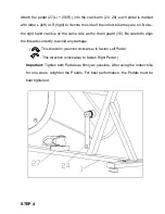
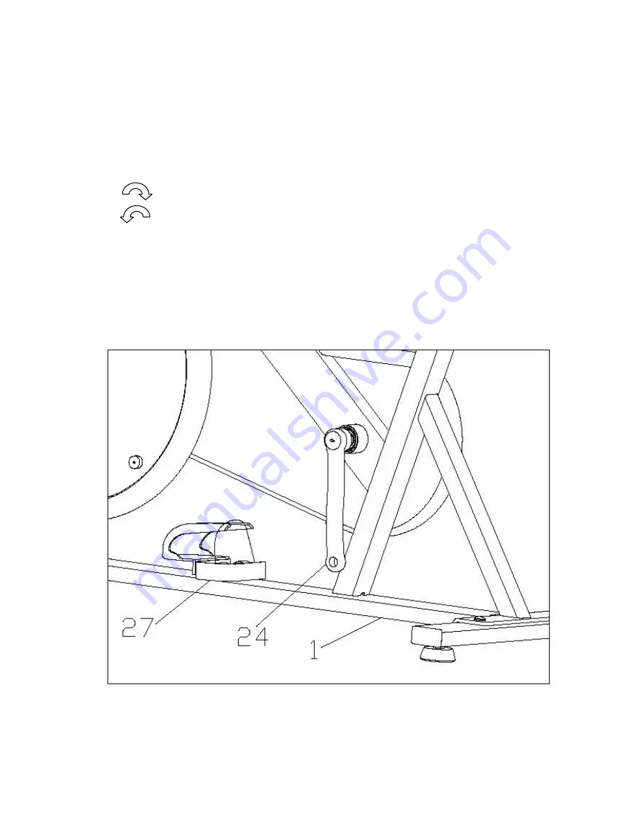
Attach the pedal (27(L) + 29(R) ) into the crank arm (24, 28), each pedal is marked 

with letter L (left) or R (right) to denote the side of the indoor bike they are on, Note 

– 

the right hand crank is on the same side as the chain guard (30). Be careful to align 

the threads correctly to avoid any damage.     

  (          : This direction (counter clockwise) to fasten Left Pedal.


          : This direction (clockwise) to fasten Right Pedal. ) 

Important: 

Tighten both Pedals as firmly as possible. After using the indoor bike 

for  one  week,  retighten  the  Pedals.  For  best  performance,  the  Pedals  must  be 

kept tightened.


STEP 4 

Summary of Contents for S420 FRW

Page 1: ...91107 BENEFIT S420 FRW INDOOR BIKE ASSEMBLE ...

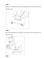
Page 2: ... 1 Attach the front Stabilizer 4 to the frame using two M8 X 25mm Bolt 52 and two Flat washers 53 STEP 2 Attach the Rear Stabilizer 5 to the frame using two M8 X 25mm Bolt 52 and two Flat washers 53 STEP 3 ...

Page 3: ...is on the same side as the chain guard 30 Be careful to align the threads correctly to avoid any damage This direction counter clockwise to fasten Left Pedal This direction clockwise to fasten Right Pedal Important Tighten both Pedals as firmly as possible After using the indoor bike for one week retighten the Pedals For best performance the Pedals must be kept tightened STEP 4 ...

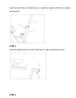
Page 4: ...Insert the Seat Post 2 into the Frame 1 adjust the height and then fix in position with Knob 51 STEP 5 Insert the Seat Bracket 3 into the Seat Post 2 and fix using the knob 51 STEP 6 ...

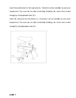
Page 5: ...he seat can be slide horizontally following the arrow then rocked strongly by the adjustable knob 51 Insert the seat post 2 into frame 1 10 position can be available as per use s requirement The seat can be slide horizontally following the arrow then rocked strongly by the adjustable knob 51 STEP 7 ...

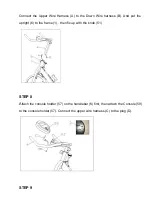
Page 6: ...Wire harness B And put the upright 6 to the frame 1 then fix up with the knob 51 STEP 8 Attach the console holder 57 on the handlebar 6 first then attach the Console 59 to the console holder 57 Connect the upper wire harness C to the plug D STEP 9 ...

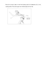
Page 7: ...Prevent the sensor cable to touch the flywheel while the handlebar 6 is in the lowest position Pull out the upper wire harness 56 from the hole ...

Page 8: ......

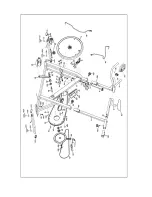
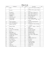
Page 9: ...41 M8 Nut 13 6 13 Spring of Adjustment 1 42 ψ16 ψ8 5 T1 5 M8 ARC Washer Flywheel 6 14 Spring of Washer 1 43 Adjustable Stabilizer End Cap M8 26 4 15 M5 15 Bolt 6 44 Moving Wheel 2 16 ψ10 ψ5 5 T1 0 M5 Washer 8 45 Bolt of Moving Wheel 2 17 M6 Nut 1 46 M8 Mylon Locknut 2 18 M6 Locknuts 1 47 Stabilizer End Cap 4 19 Water Bottle Holder 1 48 Seat of Induce Mucus 1 20 Crank Bearing of right Set 1 49 M4 1...

Reviews: