background image

27.1.1999 

8dds50gb_fm5.fm

 5

Product: DDS-50(Office set) /     YO0311

V10

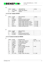
8.1.2.2 Led module OO0301

V1

V2

8.1.2.3 Connector module OO0302

V1

PIN #

NAME

DESCRIPTION

LEVEL

1

HF_SPKR

Hands Free speaker

2

GND

ground

PIN #

NAME

DESCRIPTION

LEVEL

1

GND

ground

2

HS_MIC

Handset microphone signal

3

HS_ERP

Handset earphone signal

4

PH_R

phone charge indicator led, red

0 / 5 VDC

5

PH_G

phone charge indicator led, green

0 / 5 VDC

6

B_R

battery charge indicator led, red

0 / 5 VDC

7

B_G

battery charge indicator led, green

0 / 5 VDC

8

SWITCH

battery discharge switch

0 / 5 VDC

PIN #

NAME

DESCRIPTION

1

GND

ground

2

HS_ERP

Handset earphone signal

3

HS_MIC

Handset microphone signal

PIN #

NAME

DESCRIPTION

LEVEL

1

V_CHG

charge current for phone

max. 10 V, 1.5 A

2

V_BATT

mobile battery voltage

3

EXTMIC

microphone signal

4

GND

ground

5

EXTERP

earphone signal

6

CADET

office kit indicator for phone

5 VDC

7

I2CINT

I2C bus interrupt

8

SCL

I2C bus clock

9

SDA

I2C bus data

10

TxD

RS-232 TxD

11

RxD

RS-232 RxD

12

PH_CTRL

charger control from phone

0 - 5 VDC

Summary of Contents for SIGMA GOLD TDP-52-SN3

Page 1: ...27 1 1999 Dp_52ngbTOC fm 1 Product TDP 52 SN3 SERVICE MANUAL BENEFON SIGMA GOLD TDP 52 SN3 ...

Page 2: ...acturer 1 3 1 2 PRODUCT FAMILY 1 4 2 0 OWNER S MANUAL 2 1 3 0 INSTALLATION INSTRUCTIONS 3 1 3 1 Phone Programming 3 1 3 1 1 To program Using the Phone Keys 3 1 3 1 2 To program Using the BeneLoc Program 3 3 3 2 CAR KIT INSTALLATION 3 5 3 2 1 Antenna 3 5 3 2 2 Phone Holder KDS 50 3 5 3 2 3 Microphone 3 5 3 2 4 Cable 3 5 3 2 5 External Handset HDS 50 3 5 3 2 6 Car Box UDH 50 3 6 3 2 7 Hf Speaker 3 6...

Page 3: ... PHONE S CONSTRUCTION 5 1 5 1 LOGIC AUDIO 5 2 5 1 1 General 5 2 5 1 2 Connectors 5 3 5 1 3 Circuit Diagram 5 5 5 1 4 Functions 5 6 5 1 5 Function Description 5 10 5 1 6 TX audio 5 10 5 1 7 RX Audio 5 11 5 1 8 FII Signal 5 11 5 1 9 FFSK Modem 5 11 5 1 10 The DTMF Generator Receiver 5 12 5 1 11 Signal level detectors 5 12 5 1 12 Compander Expander 5 12 5 1 13 Alarm buzzer 5 12 5 1 14 Audio signals f...

Page 4: ...INS CHARGER CMA 50 230 6 2 6 2 LIGHTER SOCKET CHARGER CCS 50 12 6 3 7 0 CAR ASSEMBLY KIT 7 1 7 1 CARBOX UDH 50 7 2 7 1 1 Including attached functions 7 2 7 1 2 Connector descriptions 7 2 7 1 3 Parts list OO0700 7 5 7 2 CARBOX UDH 50 7 16 7 2 1 Including attached functions 7 16 7 2 2 Connector descriptions 7 16 7 2 3 Parts list OW0700 7 19 7 2 4 System Cable 7 32 7 3 HANDS FREE CRADLE KDS 50 7 33 7...

Page 5: ...0 8 23 8 2 1 External Handset not serviceable 8 23 8 2 2 General 8 24 8 2 3 Connector XIN Signals 8 25 8 2 4 Microphone 8 25 8 2 5 Speaker 8 25 8 2 6 Hook 8 25 8 2 7 Parts list OO0009 8 26 9 0 OTHER ACCESSORIES 9 1 9 1 LINE INTERFACE LIF 40 9 2 9 1 1 General 9 2 9 1 2 Using the line interface 9 2 9 1 3 Technical information 9 3 9 1 4 Manufacturers Declaration for BABT SITS 85 22 9 7 9 1 5 Parts li...

Page 6: ...urrent 2 mA Standby current 60 mA Conversation mode high power app 0 9 A Conversation mode low power app 0 4 A Charger automatic 1 h rapid charging for NiCd or NiMH batteries 1 1 4 Accessories hands free car kit carbox holder car radio mute external antenna microphone loudspeaker external alert light holder portable hands free line interface mains charger cigarette lighter charger office set branc...

Page 7: ...phabetical or numerical order writing in memory during a call Repeat last dialled number or one of 6 numbers from the quick memory locations 1 1 7 Clock time and date display real time alarm setting real time power on setting real time power off setting elapsed conversation time counter both incoming and outgoing received call counter and time display 1 1 8 Pager answers incoming calls and receive...

Page 8: ...ge memory Field strength indicator Battery saving function Menu structure for user customisation Automatic Prefix Management APM Keys lockable to prevent accidental operation Phone code to prevent unauthorised use SIS protection function CLIP calling line identity presentation international prefix 1 1 10 Additional Exchange Based Features R function Register recall MFT function DTMF signal transmi...

Page 9: ... for hands free function car radio mute and external alert facility EXTERNAL HANDSET WITH HOLDER HDS 50 This is an optional accessory for the hands free car kit LINE INTERFACE LIF 40 To connect to the mobile phone any appliance using DTMF or MFT dialling such as the home telephone wireless phone answering machine telefax or modem and microcomputer BRANCHING UNIT DB 40 With a branching unit two dif...

Page 10: ...27 1 1999 2DP_52GB 5 Product TDP 52 SN3 General Mains charger Benefon Sigma Gold Cigarette lighter charger Light holder Antenna adapter LIGHT CAR KIT CMA 50 230 KDC 50 CCS 50 12 ...

Page 11: ...9 2DP_52GB 6 Product TDP 52 SN3 General HANDS FREE CAR KIT Carbox Antenna External handset with holder HDS 50 Loudspeaker Micro phone Car Radio Mute External Alert 12 24V Benefon Sigma Gold Holder KDS 50 UDH 50 ...

Page 12: ...27 1 1999 2DP_52GB 7 Product TDP 52 SN3 General Line interface Branching unit LIF 40 DB 40 ...

Page 13: ...27 1 1999 2DP_52GB 8 Product TDP 52 SN3 General OFFICE SET OFFICE SET Mains Line Benefon Sigma Gold Telefax Telephone Micro Modem Spare battery charger DDS 50 interface computer ...

Page 14: ...27 1 1999 2DP_52GB 9 Product TDP 52 SN3 General Belt clip Hand strap Portable hands free BeneWin ...

Page 15: ...1user_gb fm 1 2 0 OWNER S MANUAL ...

Page 16: ... 2 Press and the following text will appear in the display BENEFON will be flashing in the display 3 1 1 1 Sales Date 1 Choose SELECT The following text will appear in the display SALES DATE XXXXXX 2 Choose CHANGE XXXXXX will be replaced by the date daydaymonthmonthyearyear Remember to check that the date is correct If the date is correct choose SAVE If the date is incorrect delete it by choosing ...

Page 17: ...NGE Enter the radio path identification ten digits and save the identification by choosing SAVE Remember to check that the radio path identification is correct 3 1 1 3 Phone Code 1 Press and the following text will appear in the display PHONE CODE XXXX 2 Choose CHANGE Enter the phone code four digits and save the code by choosing SAVE 3 1 1 4 Closing Instructions 1 Having programmed the necessary ...

Page 18: ...1 2 To program Using the BeneLoc Program Start the installed program by clicking the icon The phone must be connected to the system as discribed above Main window Press Dealer key to enter the programming window GE N M ET ER PH ONE COM 1 COM 2 ...

Page 19: ... SN3 You can read the phone data by pressing the Read phone key You can change the miscellanous settings with the computer and transfer them to phone by pressing the Program phone key BeneLoc includes Help program for further information ...

Page 20: ...lace you have chosen and then install the phone holder in the installation base 3 2 3 Microphone Install the microphone so that it is aimed directly at the user and comes as close as possible to the user s mouth A good place for the microphone is near the rearview mirror where the noise level is lower than for example beside a windshield pillar It is also possible to install the microphone on a su...

Page 21: ...ox Install the car box so that the heat sink has some space for cooling The car box has holes which enable you to fasten the car box with a cable tie The installation material bag also contains adhesive band fasteners 3 2 7 Hf Speaker Install the speaker in a suitable place near the floor of the car To avoid echo remember to pay attention to the position of the microphone as well ...

Page 22: ...rey 3 Ground Black 4 External Alert active low Brown 5 Hf Speaker Grey 6 Vbatt 12 24 V Red External Alert Car Radio Mute See the installation instructions of your car radio UDH 50 KDS 50 HDS 50 Vbatt 12 24V Car Radio External Alert Mute Installation base Installation base fuse open Hf Speaker ACC to the 12 V power terminal which is energized in the accessory position of the ignition key VB Externa...

Page 23: ...level of the microphone by using the CAR KIT TUNING option The level is correct when the microphone path is activated by voice alone and not for example by background noise in your car or office The following figure shows you the CAR KIT TUNING setup process You can set up the OFFICE SET TUNING following the same procedure a If the CAR KIT TUNING is set too high your voice 1 will not activate the ...

Page 24: ...e low c When the CAR KIT TUNING has been set correctly only your voice 1 3 will open the microphone path Benefon phones have been set in our factory so that they will function in most cars The factory setting for the CAR KIT TUNING is 38 and for the OFFICE SET TUNING 42 The recommended adjustment range is 5 units from the factory setting C ar kit tuning 2 50 40 30 3 C ar kit tuning 50 40 30 2 1 ...

Page 25: ...obtain the smallest difference between the amplification and attenuation of the microphone and speaker This means that the connection is almost bidirectional If the HF function easily creates feedback decrease the value of the CAR KIT SWING OFFICE SET SWING By turning down the volume it is possible to reduce the occurance of feedback b With a tuning value of 1 it is possible to obtain the greatest...

Page 26: ...n the display CAR KIT SWING 1 4 3 The figure can be different 8 Choose SELECT and the following text will appear in the display CAR KIT SWING 1 4 3 3 is blinking 9 Enter one digit and OK Tuning in car kit 1 Connect the localbox to your phone and turn the phone on 2 Press and the following text will appear in the display BENEFON will be flashing in the display 3 Connect the hand portable to the car...

Page 27: ... enables you to check at a glance your current settings Your personal settings and phone numbers stored on the hard disk can be trans ferred to the mobile phone whenever necessary When you travel or use a borrowed phone your own settings make the phone feel like your own The main functions of the BeneWin Program are divided into two windows the BeneWin SCM window in which you can modify the phone ...

Page 28: ...tinue Setup choose the Continue button To quit Setup choose the Exit Setup button Next the Setup Program will ask you to specify the drive and directory in which you want to install the BeneWin Program The Program suggests the following C BENEWIN Accept the drive and directory by clicking the Continue button You can quit Setup by clicking the Exit Setup button The Setup Program creates a BENEWIN d...

Page 29: ...an start the BeneWin Program To start the BeneWin Program double click the BeneSCM icon If the phone has not been connected to the computer and you start the Program the following error message will appear on the screen FATAL COMMUNICATION ERROR You will however be able to modify the data stored in your computer s memory locations by clicking the OK button If you use a laptop computer make sure th...

Page 30: ... to work 4 2 1 Installation of Beneloc program Start Windows Close all other programs except Program Manager Insert Beneloc Installation Disc 1 in the floppy disk drive of your computer In the Program Manager window choose Run from File menu Type the letter A or B to indicate your floppy disc drive and then type SETUP EXE For example A SETUP EXE Click the OK button and follow the instructions disp...

Page 31: ...OM2 The serial ports are usually located in the back of your computer and more precise instructions can be found in the manual accompanying the computer Switch off the phone Plug the cable with flat connector into the connector at the bot tom of the phone When the cable has been connected and the phone is switched on the phone should be in LOCAL mode You can test this by pressing arrow button Ther...

Page 32: ...u can not change the tuning values from Help menu Dealer From Dealer submenu you can make or check programming of the phone You will also find the SIS information from Dealer submenu Service You can control the audio lines for example switch Rx audio and compander on off in the Service main menu It is also possible to control the phone to desired channel There is also possible to change the power ...

Page 33: ... of your computer which is called COM1 or COM2 The serial ports are usually located in the back of your computer and more precise instructions can be found in the manual accompanying the computer It is recommended to use external power supply when transferring software to phone with WinFlash If it is impossible to use external power supply the battery of phone must be fully charged NOTE Before sta...

Page 34: ...ware you want to transfer to phone by clicking it In the right side win dow you will find some information of the selected software Click Execute to start software transferring to phone Follow the instructions shown in the screen You can reset the phone by removing the flat connector from the phone and attaching it back again Be sure that there are no marks on the display before pressing enter ...

Page 35: ... MF 1502 A NC 2108 AV 0001 MC0806 MC0808 MC0810 MC0812 MC0814 MC0824 Color Black Blue Red Grey Green Wooden effect Code A B AM 0062 OY0725 OY0785 OD0725 OD0785 Version Nordic Poland Code D F Version Code YA0070 Nordic Poland dg0102 ds4 MC0836 MC0837 MC0840 MC0838 MC0839 MC0841 ...

Page 36: ...y the RF signals have a different path and the keyboard has a different unit The processor controls the audio and radio modules internal devices and external accessories The processor includes CPU 68HC11A1 8 bit 8 A D 512 8 EEPROM 256 8 RAM I O PROM 28F020 256 8 EEPROM program memory RAM 62256 8K 8 CMOS RAM number memory ASIC IA8001 32 pcs out and 14 pcs inp 3 series out 3 analog out frequency cou...

Page 37: ...ms 9 SRSSI RX signal strength indicator analog 0 5V 10 GND ground 11 S450K 450kHz for AFC measurement approx 1Vpp 12 GND ground 13 SDTUNE not function 14 SSPARE not function 15 VB power supply from the battery 6V 16 VB 17 VB 18 STXBIAS TX initiate 0V TX OFF 0 5V 19 STXPWR TX power control analog 0 5V 20 STXAUDIO TX audio signal 220 mVrms 1 VB power supply from battery 6V 2 VB 3 VB 4 VB 5 VB 6 EXTM...

Page 38: ... XKEYOUT0 key matrix output 0 5V 27 XKEYOUT1 28 XKEYOUT2 29 XKEYOUT3 30 XCHGIND charging voltage indicator 0 5V 31 XBMEM input memory data line from the bat tery 0 5V 32 nc 33 nc 34 MICINPUT microphone line 35 nc 36 XISIGN battery voltage course indicator 0 5V 37 KEYLEDVB voltage for the led of keyboard 6V 38 IVBDET battery current indicator 0 5V 39 V PROG battery charging voltage 40 V PROG ...

Page 39: ...oltage 5V 2 RES reset line 0 5V 3 CSI display data input 0 5V 4 AO 5 SCL clock line for data 0 5V 6 SI 7 GND ground 8 CONT not function 9 GND 10 LED supply voltage for led of display 11 KEYOUT1 key matrix output volume key 0 5V 12 KEYINP4 13 KEYINP4 key matrix input volume keys 0 5V 14 KEYOUT0 key matrix output volume key 0 5V 15 PWRKEY powerkey 16 GND 1 VCC supply voltage 5V 2 REC record control ...

Page 40: ...th series and parallel I O lines The clock oscillator is located in the audio circuit and provides the CPU with a 7 2 MHz clock signal The CPU divides this by 4 to get timing signal E When the processor is operating RESET 5V VCC 5V E 1 8 Mhz AS R W and A0 A15 pulses should be 0 5V no intermediate values only 0 or 5V OA0701A module connector pins OA0701B power supply OA0701C cpu ASIC RAM EPROM OA07...

Page 41: ... same detector also serves to control the HF function 5 1 4 4 AFC The AFC function is performed by an internal ASIC frequency counter A 450 kHz intermediate frequency is amplified to a square wave form by Q305 The frequency is adjusted by ASIC pulse frequency modulated signal D A 0 which is integrated by C378 This approx 2 5V DC voltage is fed to the synthesiser AFC pin 5 1 4 5 Sleep Timer The pho...

Page 42: ...y pack change by the battery B201 5 1 4 9 Battery Voltage Measurement The battery voltage is measured by an A D converter The converter 256 step conversion scale is not sufficient as it stands so the measured range is restricted to 5 8V by the operational amplifier I303 The reference voltage for the measurement is provided by the processor regulator 5V supply Calibration is done by the program aga...

Page 43: ...battery voltage and time measurement 5 1 4 14 Temperature Measurement The radio has two separate temperature sensors one within the battery pack and the other within the radio module Inside the radio the NTC resistor R316 voltage is measured by the processor A D converter This value is converted by a programmed table to a temperature reading 5 1 4 15 Real time Clock A real time clock is provided w...

Page 44: ...ut signal and transmit DTMF signal VR1 is a programmable amplifier which sets the microphone signal sensitivity to the correct level After VR1 comes band pass filter for transmitting the voice signal After the TXBPF is the summing junction AMP6 of the tx signal and transmit answer signal ANAOUT TXDET is the transmit voice signal detection circuit which works as a full wave rectifier Next comes ATT...

Page 45: ...n be bypassed The linearity is adjustable by the control register EVR VR6 is a gain control circuit to set the rx audio signal to the correct level After VR6 comes the RXMUTE switch which is operated by the RXMUTE control ADD4 is the summing junction of the rx audio signal external signal not used DTMF signal and transmit signal VR10 is the volume control circuit to set the level of earphone and e...

Page 46: ...hone and external earphones When transmitting a numeric message the DTMF tones produced by the generator are fed through the VR8 which set the DTMF signal level to the switch DTMFTXON and then the signal is summed with the tx audio signal The DTMF receiver takes in numeric messages sent to the phone The route to the DTMF receiver splits from the rx audio signal after the summing junction ADD4 5 1 ...

Page 47: ... audio signal from the answer module comes to the summing junction AMP6 5 1 15 The other in audio asic I405 OSC is the main oscillator and clock divider for the prosessor CLKBUF is clock buffer generate clock out from main clock INTERFACE DATA REGISTER is a 16 bit address data serial interface circuit BIAS is bias current generator for amplifiers TIMER is an 8 bit timer not used DA1 DA2 DA3 are 8 ...

Page 48: ...nF 10 50 V X7R Philips CF0223 C316 SMD capasitor 22 nF 10 50 V X7R Philips CF0223 C334 SMD capasitor 22 nF 10 50 V X7R Philips CF0223 C351 SMD capasitor 22 nF 10 50 V X7R Philips CU1106 C352 SMD tantal 10uF 16V AVX TAJB106M016R CF0223 C353 SMD capasitor 22 nF 10 50 V X7R Philips CF0223 C360 SMD capasitor 22 nF 10 50 V X7R Philips CF0103 C365 SMD capasitor 10 nF 10 50 V X7R Philips CF0220 C367 SMD ...

Page 49: ...C11A8 FU LF0003 L150 EMI filter 50MHz 65ohm 40 Murata BLM11B141DPTM00 LF0003 L151 EMI filter 50MHz 65ohm 40 Murata BLM11B141DPTM00 LF0003 L160 EMI filter 50MHz 65ohm 40 Murata BLM11B141DPTM00 QS0858 Q101 SMD transistor PNP 0 1A 30V hFE 125 800 Philips BC858BW QS0848 Q102 SMD transistor NPN 0 1A 30V hFE 110 800 Philips BC848BW 115 QS0858 Q105 SMD transistor PNP 0 1A 30V hFE 125 800 Philips BC858BW ...

Page 50: ...W Kamaya RF0102 R166 SMD resistor 1 k 5 0 125 W Kamaya RF0331 R170 SMD resistor 330 R 5 0 125 W Kamaya RF0103 R171 SMD resistor 10 k 5 0 125 W Kamaya RF0103 R172 SMD resistor 10 k 5 0 125 W Kamaya RF0104 R175 SMD resistor 100 k 5 0 125 W Kamaya RF0104 R176 SMD resistor 100 k 5 0 125 W Kamaya RF0104 R177 SMD resistor 100 k 5 0 125 W Kamaya RF0224 R201 SMD resistor 220 k 5 0 125 W Kamaya RF0103 R202...

Page 51: ...a RF0106 R368 SMD resistor 10 M 5 0 125 W Kamaya RF0102 R375 SMD resistor 1 k 5 0 125 W Kamaya RF0104 R376 SMD resistor 100 k 5 0 125 W Kamaya RF0103 R378 SMD resistor 10 k 5 0 125 W Kamaya RF0103 R379 SMD resistor 10 k 5 0 125 W Kamaya RF0103 R380 SMD resistor 10 k 5 0 125 W Kamaya RF0223 R401 SMD resistor 22 k 5 0 125 W Kamaya RF0104 R402 SMD resistor 100 k 5 0 125 W Kamaya RF0104 R403 SMD resis...

Page 52: ...125 W Kamaya RF0103 R512 SMD resistor 10 k 5 0 125 W Kamaya RF0103 R513 SMD resistor 10 k 5 0 125 W Kamaya RF0103 R514 SMD resistor 10 k 5 0 125 W Kamaya RF0103 R515 SMD resistor 10 k 5 0 125 W Kamaya VN0017 V101 SMD B B connector 2x20 pin JAE IL312 40SB VF30 VM0220 V102 SMD connector male 20pin Suyin 12757A 20G2 X32765 X305 SMD Crystal 32 768kHz 20ppm Citizen CM200 X14400 X401 SMD crystal 14 4MHz...

Page 53: ...27 1 1999 4A0701GB __1 19 Product TDP 52 SN3 Sigma Gold OA0701 Proc The Top Side Layout PA0700 A5 ...

Page 54: ...27 1 1999 4A0701GB __1 20 Product TDP 52 SN3 Sigma Gold OA0701 Proc The Bottom Side Layout PA0700 A5 ...

Page 55: ...8 GND 37 XIN 36 XOUT 35 CLKOUT 34 CKSEL2 33 CKSEL1 DA1O 49 DA2O 50 DA3O 51 AMPN 52 AMPP 53 AMPO 54 MODOUT 55 VR3OUT 56 TXRECIN 57 ATTIN 58 TXBPFO 59 MIC3 60 MIC1 61 MIC2 62 EXTIN 63 TXDET 64 AK2339 QFP64 OE 1 A11 2 A9 3 A8 4 A13 5 WE 6 VCC 7 A14 8 A12 9 A7 10 A6 11 A5 12 A4 13 A3 14 28 A10 27 CS 26 I O7 25 I O6 24 I O5 23 I O4 22 I O3 21 GND 20 I O2 19 I O1 18 I O0 17 A0 16 A1 15 A2 RAM TSOP28 A11...

Page 56: ... 16 17 18 19 20 21 22 23 24 25 26 27 28 29 30 50 49 48 47 46 45 44 43 42 41 40 39 38 37 36 35 34 33 32 31 81 82 83 84 85 86 87 88 89 90 91 92 93 94 95 96 97 98 99 100 80 79 78 77 76 75 74 73 72 71 70 69 68 67 66 65 64 63 62 61 60 59 58 57 56 55 54 53 52 51 IG8001 OE ALARM DA2 RESET 1 2 PA0 3 4 5 6 7 8 9 10 11 12 13 14 15 16 17 18 19 20 21 22 23 24 25 26 27 28 29 30 31 32 PE2 PE6 PE3 PE7 Vrl Vrh VS...

Page 57: ...27 1 1999 4A0701GB __1 23 Product TDP 52 SN3 Sigma Gold OA0701 Proc ...

Page 58: ...27 1 1999 4A0701GB __1 24 Product TDP 52 SN3 Sigma Gold OA0701 Proc ...

Page 59: ...27 1 1999 4A0701GB __1 25 Product TDP 52 SN3 Sigma Gold OA0701 Proc ...

Page 60: ...27 1 1999 4A0701GB __1 26 Product TDP 52 SN3 Sigma Gold OA0701 Proc ...

Page 61: ...27 1 1999 4A0701GB __1 27 Product TDP 52 SN3 Sigma Gold OA0701 Proc ...

Page 62: ...27 1 1999 4A0701GB __1 28 Product TDP 52 SN3 Sigma Gold OA0701 Proc ...

Page 63: ...xternal audio from the microphone 400 mVrms 7 EXTERP external audio to the speaker ampili fier 220 mVrms 8 CADET carbox identification 0 5V 9 I2CINT i2c interrupt radio input 0 5V 10 SGL i2c clock 0 5V 11 SDA i2c data 0 5V 12 TXD rs232 out 0 5V 13 RXD rs232 in 0 5V 14 EXTIO reserve 0 5V 15 CHGCONT charging control voltage 0 4 2V 16 GND ground 17 GND 18 GND 19 GND 20 GND 21 XKEYINP0 key matrix inpu...

Page 64: ...DET battery current indicator 0 5V 39 V PROG battery charging voltage 40 V PROG 1 SV CHG battery charging voltage IN 2A 2 SV CHG battery charging voltage IN 2A 3 VB 6 V output to accessories 0 5A 4 V PROG FLASH PROM programming voltage IN 0 5 12 VDC 5 SEXT MIC PWR external audio from the microphone 400 mVrms 6 GND 7 GND 8 EXTERPX HOOK external audio to the speaker amplifier 220 mVrms 9 SCADET carb...

Page 65: ... 0 125 W Kamaya RF0101 R113 SMD resistor 100 R 5 0 125 W Kamaya RF0101 R114 SMD resistor 100 R 5 0 125 W Kamaya RF0101 R115 SMD resistor 100 R 5 0 125 W Kamaya RF0101 R116 SMD resistor 100 R 5 0 125 W Kamaya RF0101 R117 SMD resistor 100 R 5 0 125 W Kamaya RF0101 R118 SMD resistor 100 R 5 0 125 W Kamaya RF0101 R119 SMD resistor 100 R 5 0 125 W Kamaya RF0222 R120 SMD resistor 2 2 k 5 0 125 W Kamaya ...

Page 66: ...5 50 V NP0 Philips CF0221 T105 SMD capasitor 220 pF 5 50 V NP0 Philips CF0221 T106 SMD capasitor 220 pF 5 50 V NP0 Philips CF0221 T107 SMD capasitor 220 pF 5 50 V NP0 Philips CF0221 T108 SMD capasitor 220 pF 5 50 V NP0 Philips CF0221 T109 SMD capasitor 220 pF 5 50 V NP0 Philips CF0221 T110 SMD capasitor 220 pF 5 50 V NP0 Philips CF0221 T111 SMD capasitor 220 pF 5 50 V NP0 Philips VM0242 V100 SMD s...

Page 67: ...27 1 1999 4H0700GB __2 33 Product TDP 52 SN3 Sigma Gold OH0700 The Top Side Layout PH0700 A5 ...

Page 68: ...27 1 1999 4H0700GB __2 34 Product TDP 52 SN3 Sigma Gold OH0700 The Bottom Side Layout PH0700 A5 ...

Page 69: ...27 1 1999 4H0700GB __2 35 Product TDP 52 SN3 Sigma Gold OH0700 ...

Page 70: ...rent pulses either charge or discharge the loop filter The VCO control voltage is derived from the loop filter output The synthesizer 12 5 kHz reference frequency is made by dividing the 12 8 MHz sig nal from the temperature compensated oscillator TCXO The series form signal which controls the channel frequency comes from the audio processor module via connector V600 SDATA SCLK and SLE signals are...

Page 71: ...r circuit produces current pulses at output DO2 as a result of the phase detection The current pulses either charge or discharge the loop filter con densators The VCO control voltage is derived from the loop filter output The synthesizer 12 5 kHz reference frequency is made by dividing the 12 8 MHz sig nal from the temperature compensated oscillator TCXO The series form signal which controls the c...

Page 72: ...ge 4 75V TXAUDIO Transmitter audio signal 12 8M 12 8 MHz signal to the receiver circuit SCLK Clock signal for synthesizer control data SDATA Synthesizer control data SLE ENABLE pulse to the synthesizer TXINJ TX synthesizer output to the transmitter 6 dBm AFC AFC control voltage from AF LOGIC board TXS_REG Control line for VTXS regulator ...

Page 73: ...SAW filter X102 to the FM IF circuit I201 RX injection frequency 540 250 544 725MHz Injection level impedance 1 dBm 50 ohm The second intermediate freqency local oscillator frequency required by the FM IF circuit is generated by multiplying the 12 8 MHz reference oscillator frequency by six The multiplier circuit is made with transistor Q201 The second intermediate frequency is 450 kHz The phase s...

Page 74: ...XINJ RX injection signal to the double balanced mixer 12 8 MHz 12 8 MHz signal to the multiplier for the 2 mixer VRX RX operating voltage 4 75 V from the regula tor 450 kHz Output from 2 IF to the AFC detector RXAUDIO Receiver audio output 100mVrms RSSI Received signal strength indicator output 0 5 2V channel RF input SINAD psof 001 113 dBm 20 dB 180 113 dBm 20 dB ...

Page 75: ...TXPWR from the audio processor unit are equal The power module power control voltage must not exceed 4V I601 serves as voltage regulator for the power controller and also as the ON OFF switch for RF output power When the phone is connected to an external voltage supply the audio processor unit raises the transmitter power by approx 1 0 dB using the TXPWR control 5 3 11 Control and Output Signals O...

Page 76: ...27 1 1999 4Z0700GB __2 42 Product TDP 52 SN3 Sigma Gold OY0725 RF The Top Side Layout PY0700A3 OY0725 RF ...

Page 77: ...27 1 1999 4Z0700GB __2 43 Product TDP 52 SN3 Sigma Gold OY0725 RF The Bottom Side Layout PY0700A3 ...

Page 78: ...208 SMD capasitor 22 nF 10 50 V X7R Philips CF0100 C209 SMD capasitor 10 pF 0 25pF 50 V NP0 Philips CF0223 C210 SMD capasitor 22 nF 10 50 V X7R Philips CF0103 C211 SMD capasitor 10 nF 10 50 V X7R Philips CF0103 C212 SMD capasitor 10 nF 10 50 V X7R Philips CF0102 C213 SMD capasitor 1 nF 5 NP0 Philips CU3106 C214 SMD tantal 10uF 6V 20 AVX TAJA106M006R CF0102 C215 SMD capasitor 1 nF 5 NP0 Philips CF0...

Page 79: ... CF0101 C420 SMD capasitor 100 pF 5 50 V NP0 Philips CF0223 C421 SMD capasitor 22 nF 10 50 V X7R Philips CF0109 C422 SMD capasitor 1 pF 0 25pF 50 V NP0 Philips CF0390 C423 SMD capasitor 39pF 5 50V NP0 Philips CF0101 C426 SMD capasitor 100 pF 5 50 V NP0 Philips CF0101 C428 SMD capasitor 100 pF 5 50 V NP0 Philips CU3106 C429 SMD tantal 10uF 6V 20 AVX TAJA106M006R CF0101 C430 SMD capasitor 100 pF 5 5...

Page 80: ...SMD pin diode Hitachi HVC132 DY0062 D610 SMD shcottky diode 40V 20mA Siemens BAT 62 IV6070 I201 FM IF system Philips SA607DK IS2335 I300 Dual freg synthesizer PLL prescaler 1 2GHz NationalSe LMX23352TMX IR1248 I380 Regulator 4 8V 240mA 2 4 Toko TK11248AM IR1248 I480 Regulator 4 8V 240mA 2 4 Toko TK11248AM IR1248 I601 Regulator 4 8V 240mA 2 4 Toko TK11248AM IA7550 I610 Single op amp Toshiba TA 75S0...

Page 81: ... 22 R 5 0 125 W Kamaya RF0473 R209 SMD resistor 47 k 5 0 125 W Kamaya RF0393 R210 SMD resistor 39 k 5 0 125 W Kamaya RF0683 R211 SMD resistor 68 k 5 0 125 W Kamaya RTN223 R212 SMD NTC resistor 22k 10 B 3924 Hokuriku 157 223 45001TP RF0682 R213 SMD resistor 6 8 k 5 0 125 W Kamaya RF0102 R214 SMD resistor 1 k 5 0 125 W Kamaya RF0683 R215 SMD resistor 68 k 5 0 125 W Kamaya RF0473 R216 SMD resistor 47...

Page 82: ...2 R 5 0 125 W Kamaya RF0101 R621 SMD resistor 100 R 5 0 125 W Kamaya RF0392 R622 SMD resistor 3 9 k 5 0 125 W Kamaya RF0102 R623 SMD resistor 1 k 5 0 125 W Kamaya RF0470 R624 SMD resistor 47 R 5 0 125 W Kamaya RF0391 R630 SMD resistor 390 R 5 0 125 W Kamaya RF0100 R631 SMD resistor 10 R 5 0 125 W Kamaya RF0391 R632 SMD resistor 390 R 5 0 125 W Kamaya RF0184 R640 SMD resistor 180 k 5 0 125 W Kamaya...

Page 83: ...27 1 1999 4Y0725GB 49 Product TDP 52 SN3 Sigma Gold OY0725 RF QA4931 Y421 SMD RF tarnsistor NPN 9GHz NF1 2dB G13dB Sanyo 2SC4931 B2 Last update 22 01 99 CODE PART DESCRIPT VALUE MANUF TYPE ...

Page 84: ...27 1 1999 4Y0725GB 50 Product TDP 52 SN3 Sigma Gold OY0725 RF ...

Page 85: ...27 1 1999 4Y0725GB 51 Product TDP 52 SN3 Sigma Gold OY0725 RF ...

Page 86: ...27 1 1999 4Y0725GB 52 Product TDP 52 SN3 Sigma Gold OY0725 RF ...

Page 87: ...26 1 1999 8HAR_GB fm 1 6 0 CHARGING CHARGING ...

Page 88: ...1 MAINS CHARGER CMA 50 230 The charger provides functions for charging Benefon brand mobile phones from a mains supply CONNECTOR A Connector A YO0240 YC0055 1 16 PIN CONFIGURATION 1 2 charge current max 10V 1 5A 3 5 nc 6 7 ground 8 15 nc 16 control voltage 0 5 VDC ...

Page 89: ...OCKET CHARGER CCS 50 12 The charger includes functions for using the handportable and for charging its batter ies from the car battery CONNECTOR A Connector A YO0243 YC0058 1 16 PIN CONFIGURATION 1 2 charge current max 10V 1 5A 3 5 nc 6 7 ground 8 15 nc 16 control voltage 0 5 VDC ...

Page 90: ...26 1 1999 8CARA_GB fm 1 7 0 CAR ASSEMBLY KIT CAR ASSEMBLY KIT ...

Page 91: ...rolled battery charger controls for external relays AL MUTE handsfree amplifiers PC AUX connector handset connector integrated branching unit 7 1 2 Connector descriptions 7 1 2 1 EXTVB V100 1 MUTE car radio mute max 500 mA 2 GND speaker ground 3 GND ground 4 AL external alarm control max 500 mA 5 HF_SPKR HF speaker 4 ohm 1 5 W 6 VBATT operating voltage 10 8 31 V max 3A ...

Page 92: ...ox 1 GND ground 2 NC not connected 3 HFMIC HF Microphone signal to carbox 4 GND ground 5 NC not connected 1 NC not connected 2 NC not connected 3 9V PC 9V 500 mA 4 NC not connected 5 AUX_MIC audio in 400 mV RMS 6 GND ground 7 GND ground 8 AUX_ERP audio out 200 mV RMS 9 CADET carbox detection 5V 10 I2CINT I2C interrupt 11 SCL I2C clock 12 SDA I2C data 13 TXD RS 232 14 RXD RS 232 15 EXTIO extra IO 1...

Page 93: ...witch I320 connects the HF microphone or HS microphone signal to the EXTMIC line The analog switch I322 controlled by AUX_MODE selects either microphone HS or HF or external signal source AUX_MIC to be connected to EXTMIC signal pin The analog switch I430 connects audio signal to handset earphone or HF speaker The analog switch I431 connects audio signal to connector PC AUX 8 or to HS erp HF spkr ...

Page 94: ... pF 5 50 V NP0 Philips CD0223 C200 SMD capasitor 22 nF 10 50 V X7R Philips CD0223 C201 SMD capasitor 22 nF 10 50 V X7R Philips CU1106 C202 SMD tantal 10uF 16V AVX TAJB106M016R CH0105 C203 SMD capasitor 1uF 20 80 16V TaiyoYuden EMK212 F105Z00T CH0105 C204 SMD capasitor 1uF 20 80 16V TaiyoYuden EMK212 F105Z00T CD0223 C205 SMD capasitor 22 nF 10 50 V X7R Philips CD0223 C210 SMD capasitor 22 nF 10 50 ...

Page 95: ...nsil 33V71500W SGS Thomso SM15T33A IR1317 I200 Adjustable regulator 1 2 37V 1 5A National S LM317AT IR2951 I210 Regulator 100mA 5V adj 5 National LP2951CM II8574 I220 8 bit I O I2C Philips PCF8574T IA7550 I300 Single op amp Toshiba TA 75S01F TE85L IC0453 I320 SMD 2x multip demultip Toshiba TC4W53F TE 12L IA7550 I321 Single op amp Toshiba TA 75S01F TE85L IC0453 I322 SMD 2x multip demultip Toshiba T...

Page 96: ...125 W Kamaya RD0473 R400 SMD resistor 47 k 5 0 125 W Kamaya RD0104 R401 SMD resistor 100 k 5 0 125 W Kamaya RD0104 R402 SMD resistor 100 k 5 0 125 W Kamaya RD0104 R403 SMD resistor 100 k 5 0 125 W Kamaya RD0333 R404 SMD resistor 33 k 5 0 125 W Kamaya RD0103 R405 SMD resistor 10 k 5 0 125 W Kamaya RD0101 R410 SMD resistor 100 R 5 0 125 W Kamaya RD0103 R411 SMD resistor 10 k 5 0 125 W Kamaya RD0339 ...

Page 97: ...2 V104 SMD system connector 1x16 pin AMP 188227 1 VM0116 V105 Contact strip angle 2x8 NB electr H4 6 16G OW0022 V106 Charger module 6V 2A Powerfinn LF0061 X100 SMD EMI suppression filt 4700pF 2A 1 6x6 8mm Murata NFM61R30T472 LF0061 X101 SMD EMI suppression filt 4700pF 2A 1 6x6 8mm Murata NFM61R30T472 Last update 14 05 97 CODE PART DESCRIPT VALUE MANUF TYPE ...

Page 98: ...27 1 1999 8udh50gb_fm5 fm 9 Product UDH 50 Carbox OO0700 The Top Side Layout PW0700B2 ...

Page 99: ...27 1 1999 8udh50gb_fm5 fm 10 Product UDH 50 Carbox OO0700 The Bottom Side Layout PW0700B2 ...

Page 100: ...27 1 1999 8udh50gb_fm5 fm 11 Product UDH 50 Carbox OO0700 A2 ...

Page 101: ...27 1 1999 8udh50gb_fm5 fm 12 Product UDH 50 Carbox OO0700 A2 ...

Page 102: ...27 1 1999 8udh50gb_fm5 fm 13 Product UDH 50 Carbox OO0700 A2 ...

Page 103: ...27 1 1999 8udh50gb_fm5 fm 14 Product UDH 50 Carbox OO0700 A2 ...

Page 104: ...999 8udh50gb_fm5 fm 15 Product UDH 50 Carbox YO0702 Mechanics YO0702 Mechanics OO 0700 NC 2008 MD 0702 MF 1502 NG 0012 MF 1140 MD 0703 NC 2010 NF 0200 NG 0011 NC 2066 NG 1015 UDH 50 Carbox YO0702 8 pcs 2 pcs ...

Page 105: ...rolled battery charger controls for external relays AL MUTE handsfree amplifiers PC AUX connector handset connector integrated branching unit 7 2 2 Connector descriptions 7 2 2 1 EXTVB V100 1 MUTE car radio mute max 500 mA 2 GND speaker ground 3 GND ground 4 AL external alarm control max 500 mA 5 HF_SPKR HF speaker 4 ohm 1 5 W 6 VBATT operating voltage 10 8 31 V max 3A ...

Page 106: ...ox 1 GND ground 2 NC not connected 3 HFMIC HF Microphone signal to carbox 4 GND ground 5 NC not connected 1 NC not connected 2 NC not connected 3 9V PC 9V 500 mA 4 NC not connected 5 AUX_MIC audio in 400 mV RMS 6 GND ground 7 GND ground 8 AUX_ERP audio out 200 mV RMS 9 CADET carbox detection 5V 10 I2CINT I2C interrupt 11 SCL I2C clock 12 SDA I2C data 13 TXD RS 232 14 RXD RS 232 15 EXTIO extra IO 1...

Page 107: ...itch I320 connects the HF microphone or HS microphone signal to the EXTMIC line The analog switch I322 controlled by AUX_MODE selects either microphone HS or HF or external signal source AUX_MIC to be connected to EXTMIC signal pin The analog switch I430 connects audio signal to handset earphone or HF speaker The analog switch I431 connects audio signal to connector PC AUX 8 or to HS erp HF spkr W...

Page 108: ...ilips CD0101 C139 SMD capasitor 100 pF 5 50 V NP0 Philips CD0101 C140 SMD capasitor 100 pF 5 50 V NP0 Philips CD0101 C141 SMD capasitor 100 pF 5 50 V NP0 Philips CD0223 C200 SMD capasitor 22 nF 10 50 V X7R Philips CD0223 C201 SMD capasitor 22 nF 10 50 V X7R Philips CU1106 C202 SMD tantal 10uF 16V AVX TAJB106M016R CH0105 C203 SMD capasitor 1uF 20 80 16V TaiyoYuden EMK212 F105Z00T CH0105 C204 SMD ca...

Page 109: ...5Z00T CH0105 C461 SMD capasitor 1uF 20 80 16V TaiyoYuden EMK212 F105Z00T CU0225 C462 SMD tantal 2 2uF 16V 20 4 7x2 6mm Matsushita ECST1CB 225R CU1106 C463 SMD tantal 10uF 16V AVX TAJB106M016R CD0104 C464 SMD capasitor 100 nF 10 50 V X7R Philips CE0337 C465 Al elko 330uF 16V 20 15x8mm Philips 222213555331 CE0476 C466 Al elko 47 uF 25 V 7x7mm Philips 2222 097 56479 CE0337 C467 Al elko 330uF 16V 20 1...

Page 110: ...nductor 110uH 3A R 0 07ohm Fuji SL03B111BE LA1391 L501 Choke horizintal 90uH 10 Trafocomp TJ1391 LA1391 L530 Choke horizintal 90uH 10 Trafocomp TJ1391 PW0700 PCB1 PCB for carbox Aspocomp QF9024 Q200 SMD p channel FET 60V 9A Rds 0 28 I R IRFR9024TR QF7002 Q201 SMD n channel FET 60V 0 115A Rds7 5 Siliconix 2N7002 T1 QSB858 Q230 SMD transistor PNP 0 1A 30V F 10dB Philips BC 858 B QS1054 Q231 SMD tran...

Page 111: ... 125 W Kamaya RD0473 R400 SMD resistor 47 k 5 0 125 W Kamaya RD0104 R401 SMD resistor 100 k 5 0 125 W Kamaya RD0104 R402 SMD resistor 100 k 5 0 125 W Kamaya RD0104 R403 SMD resistor 100 k 5 0 125 W Kamaya RD0333 R404 SMD resistor 33 k 5 0 125 W Kamaya RD0103 R405 SMD resistor 10 k 5 0 125 W Kamaya RD0101 R410 SMD resistor 100 R 5 0 125 W Kamaya RD0103 R411 SMD resistor 10 k 5 0 125 W Kamaya RD0339...

Page 112: ... 5 0 125 W Kamaya RD0103 R548 SMD resistor 10 k 5 0 125 W Kamaya RD0685 R549 SMD resistor 6 8 M 5 0 125 W Kamaya RD0274 R550 SMD resistor 270 k 5 0 125 W Kamaya RD0105 R551 SMD resistor 1 M 5 0 125 W Kamaya RD0102 R552 SMD resistor 1 k 5 0 125 W Kamaya RD0104 R553 SMD resistor 100 k 5 0 125 W Kamaya RD0105 R554 SMD resistor 1 M 5 0 125 W Kamaya RD0105 R555 SMD resistor 1 M 5 0 125 W Kamaya RD0104 ...

Page 113: ...27 1 1999 8UDH50GB __1_f 24 Product UDH 50 Carbox OW0700 The Top Side Layout PW0700A5 ...

Page 114: ...27 1 1999 8UDH50GB __1_f 25 Product UDH 50 Carbox OW0700 The Bottom Side Layout PW0700A5 ...

Page 115: ...27 1 1999 8UDH50GB __1_f 26 Product UDH 50 Carbox OW0700 A5 ...

Page 116: ...27 1 1999 8UDH50GB __1_f 27 Product UDH 50 Carbox OW0700 A5 ...

Page 117: ...27 1 1999 8UDH50GB __1_f 28 Product UDH 50 Carbox OW0700 A5 ...

Page 118: ...27 1 1999 8UDH50GB __1_f 29 Product UDH 50 Carbox OW0700 A5 ...

Page 119: ...27 1 1999 8UDH50GB __1_f 30 Product UDH 50 Carbox OW0700 A5 ...

Page 120: ...1999 8UDH50GB __1_f 31 Product UDH 50 Carbox YO0704 Mechanics YO0704 Mechanics OW 0700 NC 2008 MD 0702 MF 1502 NG 0012 MF 1140 MD 0703 NC 2010 NF 0200 NG 0011 NC 2066 NG 1015 UDH 50 Carbox YO0704 8 pcs 2 pcs ...

Page 121: ...100649 1 2 kpl 5 5 6 6 7 7 8 8 9 9 10 10 11 11 12 12 13 13 14 14 15 16 16 Connection 6 100611 2 CABLE CLAMP KIT 4 NC 1 1 2 2 3 3 AMP AMP MOLEX YC 1304 System cable 96222430 Hole 4 universal polarisizing pin MOLEX 40713 1 or similar contacts MOLEX 90119 2110 or similar connector housing MOLEX 90143 0016 or similar Direction A 8 16 1 9 X material PVC colour black 15 A 15 16 1 Cable clamp 1300 41 0 F...

Page 122: ...27 1 1999 8kds50gb_fm5 fm 33 Product KDS 50 Hands free Cradle YO0701 7 3 HANDS FREE CRADLE KDS 50 YO0701 7 3 1 Mechanics ...

Page 123: ...27 1 1999 8kds50gb_fm5 fm 34 Product KDS 50 Hands free Cradle YO0701 7 3 2 Module OO0702 The Top Side Layout PO0702A0 The Bottom Side Layout PO0702A0 ...

Page 124: ...27 1 1999 8kds50gb_fm5 fm 35 Product KDS 50 Hands free Cradle YO0701 KDS 50 ...

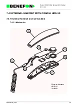
Page 125: ...27 1 1999 8HDS50GB_fm5 f 36 Product HDS 50 Ext Handset With Cradle 7 4 EXTERNAL HANDSET WITH CRADLE HDS 50 7 4 1 External Handset not serviceable 7 4 1 1 Mechanics External Handset HDS 50 YH0442 ...

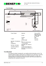
Page 126: ...Coloured PVC Colour Black BS 6748 TYPE TM2 and BT M140C Finnish Matt Length Total 5 0 2 m Coiled length 3 0 2 m Number of conductors 4 Size AWG 26 stranded wire Resistance 100 mohm m Number of strands Multiwire 30 x 0 08 mm PCW Insulation material Coloured polypropylene Strain relief Shall be firmly attached to the cable CONNECTOR HOUSING MOLEX 90123 0104 OR SIMILAR 951980 34 360 24 AWG STRANDED W...

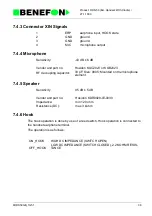
Page 127: ...ration is as follows 1 ERP earphone input HOOK state 2 GND ground 3 GND ground 4 MIC microphone output Sensitivity 43 dB 6 dB Vendor and part no Hosiden KUC2023 or KUB2023 RF decoupling capacitor 33 pF Size 0805 Mounted on the microphone element Sensitivity 95 dB 5 dB Vendor and part no Hosiden KDR0928 IE 0030 Impedance min 120 ohm Resistance DC max 3 kohm ON_HOOK HIGH DC IMPEDANCE SWITCH OPEN OFF...

Page 128: ...221 C112 SMD capasitor 220 pF 5 50 V NP0 Philips CD0221 C114 SMD capasitor 220 pF 5 50 V NP0 Philips PO0009 M100 PCB for OO0900 RP0222 R100 Edge control pot 2 2k 0 1W LOG Ruwido 0037 006 2k2 log RD0222 R102 SMD resistor 2 2 k 5 0 125 W Kamaya AR0016 S102 Reed relay Hamlin 59160 031 AE0018 XERP Assembled earphone unit 150ohm 94 3dB 60mW Hoside KDR0928 1E 0300 AM2024 XMIC Assembled microphone unit E...

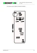
Page 129: ...27 1 1999 8HDS50GB_fm5 f 40 Product HDS 50 Ext Handset With Cradle The Top Side Layout PO0009A1 Schematic OO0009A1 ...

Page 130: ...27 1 1999 8HDS50GB_fm5 f 41 Product HDS 50 Ext Handset With Cradle The Bottom Side Layout PO0009A1 Schematic OO0009A1 ...

Page 131: ...27 1 1999 8HDS50GB_fm5 f 42 Product HDS 50 Ext Handset With Cradle HLS 41 HDS 50 HXS 40 ...

Page 132: ...27 1 1999 8HDS50GB_fm5 f 43 Product HDS 50 Ext Handset With Cradle 7 4 8 Cradle 7 4 8 1 Mechanics ...

Page 133: ...27 1 1999 8OSET_GB fm 1 8 0 OFFICE SET OFFICE SET ...

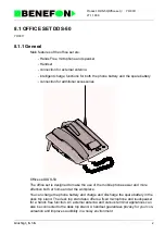
Page 134: ...es Office set DDS 50 The office set is designed to make the use of the mobile phone easier and more effective both at home and at the workplace You can charge the phone battery and charge and discharge the spare battery in the desk top stand The desk top stand also offers a fixed microphone and loudspeaker for a hands free function An external antenna and various terminal appliances can also be co...

Page 135: ...phone signal 9 nc 10 I2CINT I2C bus interrupt 11 SCL I2C bus clock 12 SDA I2C bus data 13 TxD RS 232 TxD 14 RxD RS 232 RxD 15 nc 16 VB_CTRL power supply control 0 5 VDC PIN NAME DESCRIPTION LEVEL 1 GND ground 2 HS_MIC Handset microphone signal 3 HS_ERP Handset earphone signal 4 PH_R phone charge indicator led red 0 5 VDC 5 PH_G phone charge indicator led green 0 5 VDC 6 B_R battery charge indicato...

Page 136: ...cator for phone 5 VDC 7 I2CINT I2C bus interrupt 8 SCL I2C bus clock 9 SDA I2C bus data 10 TxD RS 232 TxD 11 RxD RS 232 RxD 12 PH_CTRL charger control from phone 0 5 VDC PIN NAME DESCRIPTION LEVEL I_BATT charge current for battery max 10 V 1 5 A PIN NAME DESCRIPTION LEVEL BMEM battery pack data PIN NAME DESCRIPTION LEVEL B_TEMP battery pack temperature 0 5 VDC PIN NAME DESCRIPTION LEVEL GND ground...

Page 137: ...6 B_R battery charge indicator led red 0 5 VDC 7 B_G battery charge indicator led green 0 5 VDC 8 SWITCH battery discharge switch 0 5 VDC PIN NAME DESCRIPTION 1 GND ground 2 HS_ERP Handset earphone signal 3 HS_MIC Handset microphone signal PIN NAME DESCRIPTION LEVEL 1 V_CHG charge current for phone max 10 V 1 5 A 2 V_BATT mobile battery voltage 3 EXTMIC microphone signal 4 GND ground 5 EXTERP earp...

Page 138: ... phone max 10 V 1 5 A 3 V_BATT mobile battery voltage 4 nc 5 EXTMIC microphone signal 6 7 GND ground 8 EXTERP earphone signal 9 CADET office kit indicator for phone 5 VDC 10 I2CINT I2C bus interrupt 11 SCL I2C bus clock 12 SDA I2C bus data 13 TxD RS 232 TxD 14 RxD RS 232 RxD 15 nc 16 PH_CTRL power supply control 0 5 VDC ...

Page 139: ...r A D input Out put G3 is a PWM signal which is converted with R291 and C293 into analog DC signal This signal is used to control the output current of the power supply unit Out puts D0 and D1 are used to turn on charging current for the phone and spare bat tery P channel fets Q211 and Q221 are normally in non conducting state gate voltage tied to VB and are turned on with fets Q212 and Q222 as th...

Page 140: ... into conducting state The emitter pins of the transistors are directly connected to the anode pins of the leds 8 1 3 3 Audio The signal P1 HF_OFF of the I2C circuit I203 is used to control the analog switches I435 and I437 Q512 inverts this signal for switch I484 The inverted signal is also used for controlling the MUTE pin of the power amplifier I528 Low level sig nal turns MUTE on and high leve...

Page 141: ...ps CD0104 C127 SMD capasitor 100 nF 10 50 V X7R Philips CD0101 C130 SMD capasitor 100 pF 5 50 V NP0 Philips CD0101 C131 SMD capasitor 100 pF 5 50 V NP0 Philips CD0101 C140 SMD capasitor 100 pF 5 50 V NP0 Philips CD0101 C141 SMD capasitor 100 pF 5 50 V NP0 Philips CD0101 C142 SMD capasitor 100 pF 5 50 V NP0 Philips CD0101 C143 SMD capasitor 100 pF 5 50 V NP0 Philips CD0101 C144 SMD capasitor 100 pF...

Page 142: ... tantal 10uF 16V AVX TAJB106M016R CU0225 C501 SMD tantal 2 2uF 16V 20 4 7x2 6mm Matsushita ECST1CB 225R CE0337 C502 Al elko 330uF 16V 20 15x8mm Philips 222213555331 CH0105 C503 SMD capasitor 1uF 20 80 16V TaiyoYuden EMK212 F105Z00T CH0105 C506 SMD capasitor 1uF 20 80 16V TaiyoYuden EMK212 F105Z00T CH0105 C507 SMD capasitor 1uF 20 80 16V TaiyoYuden EMK212 F105Z00T CD0222 C520 SMD capasitor 2 2 nF 5...

Page 143: ... SMD resistor 100 R 5 0 125 W Kamaya RD0104 R210 SMD resistor 100 k 5 0 125 W Kamaya RD0104 R213 SMD resistor 100 k 5 0 125 W Kamaya RD0104 R220 SMD resistor 100 k 5 0 125 W Kamaya RD0104 R223 SMD resistor 100 k 5 0 125 W Kamaya RD0473 R230 SMD resistor 47 k 5 0 125 W Kamaya RD0103 R231 SMD resistor 10 k 5 0 125 W Kamaya RD0100 R240 SMD resistor 10 R 5 0 125 W Kamaya RD0182 R241 SMD resistor 1 8 k...

Page 144: ...W Kamaya RD0104 R465 SMD resistor 100 k 5 0 125 W Kamaya RD0333 R466 SMD resistor 33 k 5 0 125 W Kamaya RD0223 R470 SMD resistor 22 k 5 0 125 W Kamaya RD0104 R471 SMD resistor 100 k 5 0 125 W Kamaya RD0104 R473 SMD resistor 100 k 5 0 125 W Kamaya RD0103 R476 SMD resistor 10 k 5 0 125 W Kamaya RD0104 R477 SMD resistor 100 k 5 0 125 W Kamaya RD0223 R478 SMD resistor 22 k 5 0 125 W Kamaya RD0333 R480...

Page 145: ...office kit Delta DDS 40 NC2015 Y16 Cross recessed screw M2x5 DIN7985A pozidrive Ruuvitalo NC2015 Y17 Cross recessed screw M2x5 DIN7985A pozidrive Ruuvitalo NC2015 Y18 Cross recessed screw M2x5 DIN7985A pozidrive Ruuvitalo NC2015 Y19 Cross recessed screw M2x5 DIN7985A pozidrive Ruuvitalo NF0200 Y20 Nut M2 SFS2067 DIN943 Ruuvitalo NF0200 Y21 Nut M2 SFS2067 DIN943 Ruuvitalo NF0200 Y22 Nut M2 SFS2067 ...

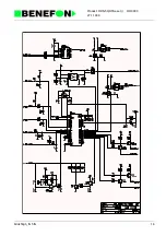
Page 146: ...27 1 1999 8dds50gb_fm5 fm 14 Product DDS 50 Office set OO0303 The Top Side Layout PO0300A0 The Bottom Side Layout PO0300A0 ...

Page 147: ...27 1 1999 8dds50gb_fm5 fm 15 Product DDS 50 Office set OO0303 ...

Page 148: ...27 1 1999 8dds50gb_fm5 fm 16 Product DDS 50 Office set OO0303 ...

Page 149: ...27 1 1999 8dds50gb_fm5 fm 17 Product DDS 50 Office set OO0303 ...

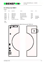
Page 150: ...pF 5 50 V NP0 Philips CD0221 C2 SMD capasitor 220 pF 5 50 V NP0 Philips CD0223 C3 SMD capasitor 22 nF 10 50 V X7R Philips DLG155 D1 SMD bicolor Green red 25mcd 20mA Citizen CL 155UR G DLG155 D2 SMD bicolor Green red 25mcd 20mA Citizen CL 155UR G VN0005 V2 Stereo jack 3 5mm Zupami 3 5 EJW C386 AS0105 V3 Tact switch h 9 5mm Alps SKHHAP PO0301 Y8 Connector PCB for office kit Delta DDS 40 Last update ...

Page 151: ...27 1 1999 8dds50gb_fm5 fm 19 Product DDS 50 Office set OO0301 ...

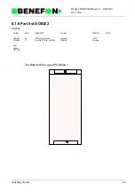
Page 152: ...duct DDS 50 Office set OO0302 8 1 6 Part list OO0302 OO0302 The Bottom Side Layout PO0302A1 CODE PART DESCRIPT VALUE MANUF TYPE VN0242 V2 SMD system conn holder AMP PO0302 Y1 Flexible PCB for OO0302 DDS 40 Simflex Last update 12 11 96 ...

Page 153: ...27 1 1999 8dds50gb_fm5 fm 21 Product DDS 50 Office set OO0302 ...

Page 154: ...27 1 1999 8dds50gb_fm5 fm 22 Product DDS 50 Office set OO0302 ...

Page 155: ...27 1 1999 8hxs40gb_fm5 fm 23 Product HXS 40 External Handset 8 2 EXTERNAL HANDSET HXS 40 8 2 1 External Handset not serviceable 8 2 1 1 Mechanics External Handset HXS 40 YH0443 ...

Page 156: ...M2 and BT M140C Finnish Matt Length Total 5 0 2 m Coiled length 3 0 2 m Number of conductors 4 Size AWG 26 stranded wire Resistance 100 mohm m Number of strands Multiwire 30 x 0 08 mm PCW Insulation material Coloured polypropylene Strain relief Shall be firmly attached to the cable CONNECTOR HOUSING MOLEX 90123 0104 OR SIMILAR 951916 35 360 24 AWG STRANDED WIRE COLOR BLACK COILED FLAT CABLE 4 8x2 ...

Page 157: ...ion is as follows 1 ERP earphone input HOOK state 2 GND ground 3 GND ground 4 MIC microphone output Sensitivity 43 dB 6 dB Vendor and part no Hosiden KUC2023 or KUB2023 RF decoupling capacitor 33 pF Size 0805 Mounted on the microphone element Sensitivity 95 dB 5 dB Vendor and part no Hosiden KDR0928 IE 0030 Impedance min 120 ohm Resistance DC max 3 kohm ON_HOOK HIGH DC IMPEDANCE SWITCH OPEN OFF_HO...

Page 158: ... C112 SMD capasitor 220 pF 5 50 V NP0 Philips CD0221 C114 SMD capasitor 220 pF 5 50 V NP0 Philips PO0009 M100 PCB for OO0900 RP0222 R100 Edge control pot 2 2k 0 1W LOG Ruwido 0037 006 2k2 log RD0222 R102 SMD resistor 2 2 k 5 0 125 W Kamaya AR0016 S102 Reed relay Hamlin 59160 031 AE0018 XERP Assembled earphone unit 150ohm 94 3dB 60mW Hoside KDR0928 1E 0300 AM2024 XMIC Assembled microphone unit Elec...

Page 159: ...27 1 1999 8hxs40gb_fm5 fm 27 Product HXS 40 External Handset The Top Side Layout PO0009A1 Schematic OO0009A1 ...

Page 160: ...27 1 1999 8hxs40gb_fm5 fm 28 Product HXS 40 External Handset The Bottom Side Layout PO0009A1 Schematic OO0009A1 ...

Page 161: ...27 1 1999 8hxs40gb_fm5 fm 29 Product HXS 40 External Handset HLS 41 HDS 50 HXS 40 ...

Page 162: ...27 1 1999 8OTHE_GB fm 1 9 0 OTHER ACCESSORIES OTHER ACCESSORIES ...

Page 163: ...nce from a powerful radio field Check this by testing with e g a magnetic antenna 9 1 1 2 Fixed line telephones Check that the telephone does not suffer interference from the handportable radio field Connect the line interface to the desired tele device Make a call from the device and move the hand phone antennna around the vicinity of the device 9 1 1 3 Cordless telephones These are not recommend...

Page 164: ...call may also be terminated by pressing the lightning key on the handportable The busy signal will then be heard from the tele device handset Do not forget to replace the tele device handset as the line interface uses power from the handport able battery 9 1 2 4 Making and receiving a call with the hand phone A call can be made and received normally from the handportable as long as the tele device...

Page 165: ... ON AT E2 speed select AT MB2400 There are tele devices that take their power from the telephone line in which case the line interface supply of 25 mA will not be enough These generally non approved devices are not recommended for use with the line interface Typically problems arise from modem or telefax internal settings see tele device operating manual Data transfer may function normally with a ...

Page 166: ...omponents R114 R115 C109 and I105 form an oscillator vibrating at a frequency of approx 220 kHz This frequency is divided within I105 into frequencies 430 Hz free reserved tone and 26 Hz ring frequency 9 1 3 6 Switched Mode Voltage Converter The basic chopper connection consists of operation amplifier I100A quad NAND I101 MOSFET Q100 and coil L100 Saw wave to the I101A input pin 2 is generated fro...

Page 167: ...as been connected to the ground so that the portable receives interruption every time the voltage is switched on 9 1 3 9 Free Reserved Tone The free reserved tone is connected by transistor Q106 to a filter consisting of the operation amplifier I100B In this filter the tone is reduced to a suitable level and the square wave received from Q106 is made more gentle 9 1 3 10 Line Switches The double f...

Page 168: ...0 VDC depending on the battery voltage of the portable ii as above iii ringing voltage 50 Vrms f 26 Hz maximum REN driving capability 1 iv free reserved tone 430 Hz I 25 5 mA b Maximum loop resistance of possible extension cable between line interface and terminal apparatus is 25 ohms c This line interface apparatus does not cause the Mobile Station to operate con trary to the requirements of BABT...

Page 169: ...e Date 21 4 1993 HJo PCF 8574 I2C address 4AH IICINT SDA SCL VB 5V REG RXAUDIO TXAUDIO DC DC Converter LPF LB LA HOOK DET 4 2 WIRE AUDIO CONV OSCILLATOR DIVIDER 74HC4060 P0 RING_OFF Input 5 5V 10V Out 15V 3V 60V 10V 25Hz 220kHz 400Hz P2 400HZ_OFF P4 HOOK_DET 5V ON HOOK P1 PWR_OFF Current sink ...

Page 170: ...uF 16V 20 6x3 2mm Matsushita ECST1CC 106R CK0680 C125 Cer capasitor 68pF 100V 10 Philips CF0680 C126 SMD capasitor 68 pF 5 50 V NP0 Philips CF0680 C127 SMD capasitor 68 pF 5 50 V NP0 Philips CF0680 C128 SMD capasitor 68 pF 5 50 V NP0 Philips CF0680 C129 SMD capasitor 68 pF 5 50 V NP0 Philips CF0822 C130 SMD capasitor 8 2nF 10 50V Philips CF0680 C131 SMD capasitor 68 pF 5 50 V NP0 Philips CF0223 C1...

Page 171: ... R110 SMD resistor 22 k 5 0 125 W Kamaya RF0103 R111 SMD resistor 10 k 5 0 125 W Kamaya RF0104 R112 SMD resistor 100 k 5 0 125 W Kamaya RF0104 R113 SMD resistor 100 k 5 0 125 W Kamaya RF0123 R114 SMD resistor 12 k 5 0 125 W Kamaya RF0223 R115 SMD resistor 22 k 5 0 125 W Kamaya RF0472 R116 SMD resistor 4 7 k 5 0 125 W Kamaya RF0222 R117 SMD resistor 2 2 k 5 0 125 W Kamaya RF0104 R118 SMD resistor 1...

Page 172: ...5 0 125 W Kamaya RF0103 R149 SMD resistor 10 k 5 0 125 W Kamaya RF0223 R150 SMD resistor 22 k 5 0 125 W Kamaya RF0103 R151 SMD resistor 10 k 5 0 125 W Kamaya RF0223 R152 SMD resistor 22 k 5 0 125 W Kamaya RF0103 R153 SMD resistor 10 k 5 0 125 W Kamaya RF0275 R201 SMD resistor 2 7 M 5 0 125 W Kamaya RC0562 R203 SMD resistor 5 6 k 5 0 125 W Kamaya VR0407 TEL Line conv modular cable Last update 07 03...

Page 173: ...27 1 1999 Xo0245e4_fm5 fm 12 Product LIF 40 Line Interface OO0245 OO0245 Component Side Layout PO0245A0 ...

Page 174: ...27 1 1999 Xo0245e4_fm5 fm 13 Product LIF 40 Line Interface OO0245 Solder Side Layout PO0245A0 ...

Page 175: ...27 1 1999 Xo0245e4_fm5 fm 14 Product LIF 40 Line Interface OO0245 ...

Page 176: ...27 1 1999 Xo0245e4_fm5 fm 15 Product LIF 40 Line Interface OO0245 ...

Page 177: ...27 1 1999 Xo0236e4_fm5 fm 16 Product DB 40 Branching Unit YO0236 9 2 BRANCHING UNIT YO0236 ...

Page 178: ...rms 6and 7 GND Ground 8 HSERP Ext audio for earphone 1 kHz 200 mVrms 9 RXD Rs232 0 5 V in 10 I2CINT I2c interruption input to radio 0 5 V 11 SCL I2c clock 0 5 V 12 SDA I2c data 0 5 V 13 CHCONT Voltage for controlling charger current 0 5 VDC analog 14 EXTIO Extra IO 1 and 2 V CHARGE Battery charging voltage 2A in 3 9V Operation voltage for accessories 0 5 A out 5 HSMIC Ext audio from microphone 1 k...

Page 179: ...o connector HS and ON HOOK audio signals to connector PC Voltage regulation is done by components R205 C207 and D201 1 and 2 V CHARGE Battery charging voltage 2 A in 3 9V Operation voltage for accessories 0 5 A out 5 PCMIC Ext audio from microphone1 kHz 400 mVrms 6 and 7 GND Ground 8 PCERP Ext audio for loudspeaker amplifier 1 kHz 200 mVrms 10 I2CINT I2c interruption input to radio 0 5 V 11 SCL I2...

Page 180: ...onnector 1x16 pin AMP 188227 1 IC0453 I201 SMD 2x multip demultip Toshiba TC4W53F TE 12L IC0453 I202 SMD 2x multip demultip Toshiba TC4W53F TE 12L PO0241 M200 PCB for juction box 60x40mm FR4 Metalex NC2005 M201 Cross recessed screw M2x5 SFS2977 DIN9652 Ruuvitalo Pozidriv NC2005 M202 Cross recessed screw M2x5 SFS2977 DIN9652 Ruuvitalo Pozidriv NC2005 M203 Cross recessed screw M2x5 SFS2977 DIN9652 R...

Page 181: ...27 1 1999 Xo0236e4_fm5 fm 20 Product DB 40 Branching Unit OO0241 OO0241 Component Side Layout PO0241A3 Schematic OO0241A3 ...

Page 182: ...27 1 1999 Xo0236e4_fm5 fm 21 Product DB 40 Branching Unit OO0241 Solder Side Layout PO0241A3 Schematic OO0241A3 ...

Page 183: ...27 1 1999 Xo0236e4_fm5 fm 22 Product DB 40 Branching Unit OO0241 ...

Reviews: