PART A: CONFIGURING SETTINGS FOR THE TRACKBOX
36 I/O SETTINGS
SETTINGS FOR DIGITAL INPUT PINS
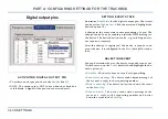
A c t i v a t i n g d i g i t a l i n p u t p i n
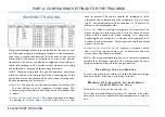
•To activate an input pin, check the
Activity
box (1).
•NOTE: The input pin is NOT in use when the check box is
left blank. A signal of the pin is not detected at all.
S e t t i n g e v e n t s t a t e
Determine
Event state
for the digital input pin. The circuit
can be set for
High
,
Low
, or
Both
. Click the arrow and high-
light the desired option (2).
A change in the event state causes grounding of a pin. An
event causing this can be, e.g. opening a door, or closing a
door. The
Both
option means that the change in the event
state is registered for both directions: E.g. the device will re-
sponse whenever a door is opened AND closed.
After the change is registered, the device responds to an
event the way, it is configured in the
Event
data field.
S e l e c t i n g e v e n t
You can determine the way, the device responds to an event.
Click the arrow on the
Event
data field and highlight the de-
sired option (3).
•
No action
: The device does not send or log anything.
•
Send status message
: The device sends status message of
the event to the corresponding status message number.
•
Write in event log
: The device only writes down the event
in the
Event log
.
•
Send and write
: The device sends status message of the
event to the corresponding status message number
and
writes down the event in the
Event log
.
NOTE: If the status message number is not configured (the
data field is left blank), the status message will be sent to the
service center number. For more information on configur-
ing status messages and their destination numbers, see
TUS MESSAGES FOR DIGITAL INPUT PINS ON PAGE 37
D e f i n i n g n o t i f i c a t i o n d e l a y
The device can be configured to allow some millseconds to
pass until the event will be registered or interpreted as a
cause for taking an action. In this case an action, such as
sending status messages and/or logging information, would
take place only in case a door is wide open for at least NN
millseconds.
Key in the time for allowed delay (4,5) in millseconds. Delay
can be set separately for
High
and
Low
, depending on which
one of the event states is in use. If you have set the pin to
register event states for
Both
directions, you can set values
for both
High
and
Low
.
Summary of Contents for TRACKBOX 2.1
Page 6: ...6 ...


