background image

08.02.2002

2gp_71gb.fm

 5

Product: TGP71EU & TGP73EU

1.11 PRODUCT FAMILY

- BENEFON TWIN HANDPORTABLE TGP71EU / TGP73EU

- MAINS CHARGER 

- CIGARETTE LIGHTER CHARGER 

- LIGHT HOLDER

- PORTABLE HANDS FREE 

- BENEWIN 

- BELT CLIP

Summary of Contents for Twin

Page 1: ...08 02 2002 Gp_71ugbTOC fm 1 Product TGP71EU TGP73EU SERVICE MANUAL Benefon Twin TGP71EU Benefon Twin DS Dual SIM TGP73EU ...

Page 2: ...services 1 3 1 9 3 T9 text input with nine keys 1 3 1 9 4 Abbreviated dialling memory 1 3 1 9 5 Recent calls memory 1 3 1 9 6 Personal organiser Clock calendar functions 1 3 1 10 Manufacturer 1 4 1 11 PRODUCT FAMILY 1 5 2 0 OWNER S MANUAL 2 1 3 0 LIGHT CAR INSTALLATION 3 1 4 0 TG Local feature description 4 1 4 1 General 4 1 4 1 1 Scope 4 1 4 1 2 Hardware requirements of TG Service software 4 1 4 ...

Page 3: ... 5 0 4 Charging battery 5 4 5 0 5 HW and SW version numbering 5 5 5 1 Logic audio 5 6 5 1 1 General description for the baseband 5 6 5 2 RF 5 10 5 2 1 General 5 10 5 2 2 Receiver 5 10 5 2 3 Transmitter 5 10 5 2 4 Synthesizer 5 10 5 2 5 Power supply and power switching 5 11 5 2 6 Antenna and antenna connector 5 11 5 2 7 Parts list OC2300 5 12 5 3 Keyboard 5 29 5 3 1 Parts list OK2300 5 29 5 4 MECHA...

Page 4: ...rts full duplex circuit switched asyn cronous data services on data rates 300 bit s 1200 bit s 4 8 kbit s 9 6 kbit s and 14 4 kbit s These data rates can be used for sending PC FAX Additionally Twin supports V 110 ISDN connection Radio Link Protocol RLP and a set of GSM 07 07 AT commands No syncronous data services and no alternate speech data calls are supported Benefon Twin supports Short Messag...

Page 5: ...y packs and operating times Initially three battery packs are available for Benefon Twin namely NiMH battery pack contains three NiMH cells and Li On battery packs one Li On cell Talk and standby times vary a lot depending on the network conditions 1 8 Accessories belt clip portable hands free kit light car cradle simple hands free kit to use in car integrated to cigarette lighter adapter charger ...

Page 6: ... nine keys While writing text into Benefon Twin user may switch T9 active and make the writing significantly easier and faster While using T9 user has to press a key only once per letter and the user interface suggests matching words to user 1 9 4 Abbreviated dialling memory Up to 255 Abbreviated Dialling entries on SIM card are supported There s no ADN memory in the phone s memory 1 9 5 Recent ca...

Page 7: ...08 02 2002 2gp_71gb fm 4 Product TGP71EU TGP73EU 1 10 Manufacturer BENEFON OYJ P O Box 84 Meriniitynkatu 11 FIN 24101 SALO FINLAND Telephone 358 2 77 400 Facsimile 358 2 332 633 ...

Page 8: ...08 02 2002 2gp_71gb fm 5 Product TGP71EU TGP73EU 1 11 PRODUCT FAMILY BENEFON TWIN HANDPORTABLE TGP71EU TGP73EU MAINS CHARGER CIGARETTE LIGHTER CHARGER LIGHT HOLDER PORTABLE HANDS FREE BENEWIN BELT CLIP ...

Page 9: ...08 02 2002 2gp_71gb fm 6 Product TGP71EU TGP73EU ...

Page 10: ...08 02 2002 2gp_71gb fm 7 Product TGP71EU TGP73EU ...

Page 11: ...1user_gb fm 1 2 0 OWNER S MANUAL ...

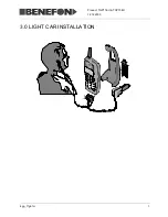
Page 12: ...12 12 2000 6gp_71gb fm 1 Product TGP71EU TGP73EU 3 0 LIGHT CAR INSTALLATION ...

Page 13: ...connect the service PC to also a Rohde Swartz CMD 55 or a Wavetek 4400M This is required for automatic tuning 4 1 3 Revision history This document is based on TG Service software version 2 1 4 2 Getting started First connect the service adapter to the PC and phone Check that the COM port set ting is correctly set in TG Service software in menu item Device Options Phone The TG Service software work...

Page 14: ...t timing is needed to get the phone to the local mode and to be sure that downloading will be completed successfully When phone has successfully entered to the local mode the display will show the phone type SW and HW versions 2 Click the leftmost Toolbar button to establish a connection between TG Service software and the phone Check the Communication trace for this While the phone is controlled ...

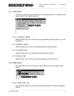
Page 15: ...on vola tile memory 4 3 1 2 Save to mobile With this option user can save the tuning parameters from the phone 4 3 1 3 Load from file With this option user can read all the tuning parameters from PC 4 3 1 4 Save to file With this option user can save the tuning parameters to a file onto PC 4 3 2 Edit menu This menu item has only one function to clear the trace box at the bottom of the window 4 3 2...

Page 16: ...s Bar on and off With the visible Sta tus Bar the user can get some help on different features and follow the signalling traffic between the PC and phone 4 3 3 3 Channel window Radio service window In this menu item the user can open a window to control the radio part Functions include setting the active TX RX and MON channels type of burst transmitted etc This window can be used only in Service m...

Page 17: ...rvice Local mode and Normal Oper ation mode 4 3 4 1 Local mode By clicking this line the user can change the phone mode to Service Local mode and back to the normal operating mode Note that this menu item can be accessed through toolbar by clicking the second button from the left 4 3 4 2 Options In this menu item user change various settings of the TG Service software The use of default settings i...

Page 18: ...ue A proper and valid battery voltage correction value is very impor tant for the battery charging algorithm The value is used to stop the charging pro cess at the right point in time 4 3 5 2 View TX tuning values This menu item allows the user to view the tuning values related to the transmitter part 4 3 5 3 View RX tuning values This menu item allows the user to view the tuning values related to...

Page 19: ... gain control values for different sig nal levels A routine for automatic adjustment with CMD 55 is available 4 3 6 3 LCD Buzzer test This menu item allows user to change the LCD contrast setting Note that too dark a setting may cause the display to flicker in the light of fluorescent tubes Buzzer test enables to check the buzzer functioning 4 3 6 4 Battery values This menu item allows the user to...

Page 20: ...08 02 2002 3gp_71sw21gb fm 8 Product TGP71EU TGP73EU Local Service 4 3 7 Help menu This menu allows the user to check the version of the TG Service software ...

Page 21: ...in the system connector pin numbering starts from the right when looking the phone from front i e the display side Note that in other TG products the system connector may be assembled upside down Another way to remember pin numbering is to know that the charging pins are the pins 17 20 i e the numbering starts as far as possible from charging connector Note that pins NMEA pins are active only in B...

Page 22: ... 3 External MIC line is used as an audio input for the mobile phone There is a DC level in this pin for headset The DC level has been made by connecting the pin to 2 2V voltage via 2 2 kohm resistor 8 RS1RX RS1 Receive Data 0V 2 7V in 9 VBAT Battery Voltage 2 7V 6 0V out 10 RS1TX RS1 Transmit Data 0V 2 7V out 11 EERPP Headset 0 VDC 1 4 VDC 0 1 VRMS AC out 12 EERPN Headset 0 VDC 1 4 VDC 0 1 VRMS AC...

Page 23: ... either the headset or the MiniHF car kit is connected to the phone When the mobile phone pulls this signal to ground it disables the accessory regulator preventing the accessory to take power With MiniHF this same feature can be used to mute the audio lines This can be done with next circuit With this circuit the 100k resistor can be omitted if the in out pin has an internal pull up when in input...

Page 24: ...ed Charger Switch 1 CHGSW1 is normally grounded and goes to logic 1 state when the charger is connected to DC jack PIN 20 Same as pin 6 The maximum current of CHARGE pin is 1 0A The maximum current of all pins except pins 6 9 and 16 20 is 10 mA 5 0 4 Charging battery During charging the charger provides a constant current that can be cut off by the phone After main charging phase phone uses short ...

Page 25: ...e SW compilation date 5 0 5 1 Hardware version HW version number consists of 8 digits like SBBRRDDZ HW version numbers are issued in alphabetical order numbers preceding letters i e later HW versions come later in alphabetical order 5 0 5 2 Software version Software version code has format X XXXXXA for example 1 290162F SW version numbers are issued in alphabetical order numbers preceding letters ...

Page 26: ...2300 5 1 Logic audio OC2300 5 1 1 General description for the baseband The baseband is built with Analog Devices components The baseband can be devided into six major parts 1 Enhanced GSM Processor 2 Voice Band Codec 3 Memory 4 Display 5 Power Ramp AFC ...

Page 27: ...ce This includes all data encoding and decoding processes as well as timing radio sub system control functions In the EGSMP there is a DSP speech codec and channel equalizer main processor Hitachi H8 300H processor and also the interfaces all the sub system of the therminal including the keypad memories display driver SIM DTE and DTA data services interface and radio Functional block diagram ...

Page 28: ...nd a speaker The baseband codec is a complete low power two channel input output port with signal conditioning The transmit path consists of an on chip burst store a GMSK modulator and two high speed DACDs with output reconstruction filters The receive path consists of two 15 bit Sigma Delta A D converters which include high performance digital filters for RF channel selection The auxiliary sectio...

Page 29: ...ssibility to be driven either in parallel or serial mode 5 1 1 5 Power management The power management is mainly handled by the Analog Device Regulator ADP3401 wich consists of four LDOs charge pump 5V for SIM card and logic level translations for SIM card 3 to 5V The chip also handles the charging of the litium battery for the real time clock The charging of main battery is made so that the charg...

Page 30: ...in Control AGC is made by changing the gain of both mixer stages and by adjusting the gain of 45 MHz second IF amplifier 5 2 3 Transmitter The TX signal is generated by dividing the 540 MHz IF VCO frequency by 2 or by 4 This 270 MHz signal 135 MHz in DCS 1800 band is then modulatid with I and Q signals The IQ modulated signal is fed to the phase comparator where it is compared to the mixed signal ...

Page 31: ... RF components is 2 8 V except dual band TX module The power on off switching is controlled from baseband processor using output enable pin of each regulator 5 2 6 Antenna and antenna connector The RF signal from antenna front end switch X403 is applied to the antenna connector V2 The antenna connector is SMA type and the nominal impedance is 50 ohm Antenna itself is a helical type dualband antenn...

Page 32: ...105X5R105K06AT CG0471 C211 SMD capasitor X7R 470pF ñ10 Murata CU1106 C212 SMD tantal 10uF 16V AVX TAJB106M016R CC2103 C213 SMD capasitor 10nF 10 100V X7R AVX 12061C103KAT2A CH0105 C215 SMD capasitor 1uF 20 80 16V TaiyoYuden EMK212 F105Z00T CH0105 C216 SMD capasitor 1uF 20 80 16V TaiyoYuden EMK212 F105Z00T CG0104 C217 SMD capasitor 100nF 10 6 3V X5R AVX CM05X5R104K06AH CG0104 C218 SMD capasitor 100...

Page 33: ...O 68pF ñ5 Murata CG0471 C3 SMD capasitor X7R 470pF ñ10 Murata CG0330 C301 SMD capasitor NPO 33pF ñ5 Murata CG0279 C302 SMD capasitor NPO 2 7pF ñ0 25pF Murata CG0129 C303 SMD capasitor NPO 1 2pF ñ0 25pF Murata CG0109 C304 SMD capasitor NPO 1 0pF ñ0 25pF Murata CG0103 C305 SMD capasitor X7R 10nF ñ10 Murata CG0221 C306 SMD capasitor X7R 220pF ñ10 Murata CG0109 C307 SMD capasitor NPO 1 0pF ñ0 25pF Mur...

Page 34: ...0100 C381 SMD capasitor NPO 10pF 0 25pF Murata CG0569 C382 SMD capasitor NPO 5 6pF ñ0 25pF Murata CG0103 C383 SMD capasitor X7R 10nF ñ10 Murata CG0220 C384 SMD capasitor NPO 22pF ñ5 Murata CG0689 C385 SMD capasitor NPO 6 8pF ñ0 25pF Murata CG0689 C388 SMD capasitor NPO 6 8pF ñ0 25pF Murata CG0331 C389 SMD capasitor X7R 330pF ñ10 Murata CG0100 C390 SMD capasitor NPO 10pF 0 25pF Murata CG0220 C401 S...

Page 35: ...ory 16MB 2MB Fujitsu MB84VD21091 85PB IM0128 I115 EEPROM 128K 16 384x8 Atmel AT24C128N 10SI2 IR3401 I120 Regulator AnalogDevi ADP3401ARU REEL IX0826 I122 EL lamp driver 4 5V 120V Supertex HV826MG IF1551 I301 RF circuit Bright II GSM Tx Rx Hitachi HD155121FEB IR2982 I302 Regulator 2 8V 50mA NationalSe LP2982IMS 2 8 IR2982 I303 Regulator 2 8V 50mA NationalSe LP2982IMS 2 8 IS1503 I304 PLL frequency s...

Page 36: ...4 R160 SMD resistor 100k 5 0 063W Kamaya RMC1 16S RG0104 R161 SMD resistor 100k 5 0 063W Kamaya RMC1 16S RG0103 R162 SMD resistor 10k 5 0 063W Kamaya RMC1 16S RG0472 R163 SMD resistor 4k7 5 0 063W Kamaya RMC1 16S RG0472 R164 SMD resistor 4k7 5 0 063W Kamaya RMC1 16S RG0472 R165 SMD resistor 4k7 5 0 063W Kamaya RMC1 16S RG0472 R166 SMD resistor 4k7 5 0 063W Kamaya RMC1 16S RG0472 R170 SMD resistor ...

Page 37: ...Kamaya RMC1 16S RG0103 R281 SMD resistor 10k 5 0 063W Kamaya RMC1 16S RG0102 R282 SMD resistor 1k0 5 0 063W Kamaya RMC1 16S RG0104 R283 SMD resistor 100k 5 0 063W Kamaya RMC1 16S RG0223 R290 SMD resistor 22k 5 0 063W Kamaya RMC1 16S RG0223 R291 SMD resistor 22k 5 0 063W Kamaya RMC1 16S RG0000 R292 SMD resistor 0 ohm RG0104 R293 SMD resistor 100k 5 0 063W Kamaya RMC1 16S RG0102 R294 SMD resistor 1k...

Page 38: ...16S RG0473 R424 SMD resistor 47k 5 0 063W Kamaya RMC1 16S RG0105 R426 SMD resistor 1M0 5 0 063W Kamaya RMC1 16S RG0563 R427 SMD resistor 56k 5 0 063W Kamaya RMC1 16S RG0104 R428 SMD resistor 100k 5 0 063W Kamaya RMC1 16S RG0472 R429 SMD resistor 4k7 5 0 063W Kamaya RMC1 16S RG0470 R430 SMD resistor 47R 5 0 063W Kamaya RMC1 16S RG0104 R431 SMD resistor 100k 5 0 063W Kamaya RMC1 16S RG0104 R432 SMD ...

Page 39: ...304 Dual Rx VCO for GSM Panasonic ENFVZ4G90 XO0473 X401 Dual Tx VCO for GSM Panasonic ENFVZ4G73 XI1519 X402 Direktional coupler Dual coupler Murata LDC15D190A0007AH ID2300 X403 Dual switch diplexer 900 1800MHz Murata LMC36 07A0501PTA PC2300 Y240 EI KOODATTU VARAS TOON Last update 08 05 00 CODE PART VALUE 1sim 2sim VI1707 V121 SIM reader X IC0454 I121 ana switch X RG0000 R292 0R X CODE PART DESCRIP...

Page 40: ...08 02 2002 4c2300gb fm 20 Product TGP71EU TGP73EU OC2300 ...

Page 41: ...08 02 2002 4c2300gb fm 21 Product TGP71EU TGP73EU OC2300 ...

Page 42: ...08 02 2002 4c2300gb fm 22 Product TGP71EU TGP73EU OC2300 ...

Page 43: ...08 02 2002 4c2300gb fm 23 Product TGP71EU TGP73EU OC2300 ...

Page 44: ...08 02 2002 4c2300gb fm 24 Product TGP71EU TGP73EU OC2300 ...

Page 45: ...08 02 2002 4c2300gb fm 25 Product TGP71EU TGP73EU OC2300 ...

Page 46: ...08 02 2002 4c2300gb fm 26 Product TGP71EU TGP73EU OC2300 ...

Page 47: ...08 02 2002 4c2300gb fm 27 Product TGP71EU TGP73EU OC2300 ...

Page 48: ...08 02 2002 4c2300gb fm 28 Product TGP71EU TGP73EU OC2300 ...

Page 49: ...capasitor NPO 33pF ñ5 Murata CG0330 C15 SMD capasitor NPO 33pF ñ5 Murata CG0330 C16 SMD capasitor NPO 33pF ñ5 Murata CG0330 C17 SMD capasitor NPO 33pF ñ5 Murata CG0330 C18 SMD capasitor NPO 33pF ñ5 Murata CG0330 C2 SMD capasitor NPO 33pF ñ5 Murata CG0330 C3 SMD capasitor NPO 33pF ñ5 Murata CG0330 C4 SMD capasitor NPO 33pF ñ5 Murata CG0330 C5 SMD capasitor NPO 33pF ñ5 Murata CG0103 C6 SMD capasitor...

Page 50: ...08 02 2002 4k2300gb fm 30 Product TGP71EU TGP73EU OK2300 ...

Page 51: ...08 02 2002 4k2300gb fm 31 Product TGP71EU TGP73EU OK2300 ...

Page 52: ...08 02 2002 4k2300gb fm 32 Product TGP71EU TGP73EU OK2300 ...

Page 53: ...12 12 2000 7gp_71gb fm 33 Product TGP71EU TGP73EU 5 4 MECHANICS ...

Reviews: