6
ČSN EN 303-5:2013 - Central heating boilers – part 5: Central heating boilers for solid fuel with manual
or automatic supply of fuel with nominal power up to 500 kW - terminology,
requirements, proofing and marking.
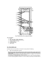
The main part of the boiler is the steel body which consists of 4 main units:
-
combustion chamber
-
combustion chamber base
-
heat exchanger
-
heat exchanger base.
All parts of the boiler body that separate combustibles from heating water and all base bearings are
made of 5 mm thick steel plates. In the front part of the boiler body, there is a combustion chamber
fitted with a burner, in the back there is a 3-pass heat exchanger. In this device, the heat from the
exhaust gas is transferred to the heating water.
The burner, which is fed from the bottom, is located in the mixer and fitted to the side wall of the base.
It consists of a cast iron elbow (“retort”) and a cast iron grate. The fuel conveyer consists of a fuel
feeding channel and a pipe for supply of burning air. Both channels are connected by a flexible piece
that serves to balance the pressure under the fire place and prevents the smoke from penetrating back
to the fuel container during the burning process.
A ceramic reflector is installed over the burner. This catalyser regulates the exhaust gas stream and
reduces dust. Through the side wall of the combustion chamber, secondary air is led into the reflector
which facilitates complete burning of fuel.
Next to the boiler, the fuel container is situated, which is connected to the worm conveyor. Its capacity
can be extended by installing an additional module (optional). Depending on the position of the
container in relation to the boiler, the boiler is produced in two versions:
right-handed version
- the container is situated on the right side of the boiler (from the front
view)
left-handed version
- the container is situated on the left side of the boiler (from the front
view)
Behind the fuel container there is an emergency extinguishing system leading into the worm feeder.
The primary combustion air ventilator is placed on the side of the boiler under the fuel container and is
connected to the mixer. The air quantity is regulated by the boiler control unit.
Both heating water input and output for connection to the heating system are situated on the outer side
of the boiler.
There are two outlets with G 2“ inner thread. The two outlets with G 3/4“ on the same
boiler side are intended for installation of drain taps - one for the combustion chamber, one for the
tubular heat exchanger. There is a smoke extension piece on the upper rear side of the boiler for the
discharge of combustion products into a chimney.
Device for extraction of combustion gases enhances the chimney draught and forms an integral part of
the boiler.
The boiler body, its cover, and the door are insulated with an insulation material that has no detrimental
effects on health. This insulation diminishes the loss due to heat interchange.
The steel plates are coloured with high quality comaxit paint.
Summary of Contents for R100
Page 1: ...1 SERVICE AND INSTALLATION MANUAL FOR CENTRAL HEATING BOILER BENEKOV R100 ...
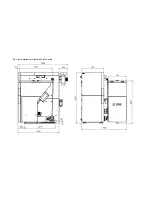
Page 8: ...Fig 2 Basic dimensions of BENEKOV R100 boiler ...
Page 9: ...Fig 3 Basic dimensions of BENEKOV R100 boiler with additional module of fuel bin ...
Page 30: ...30 Declaration of conformity of boiler BENEKOV R 100 ...
Page 31: ...31 Original ES declaration of conformity of boiler BENEKOV R 100 ...


