30
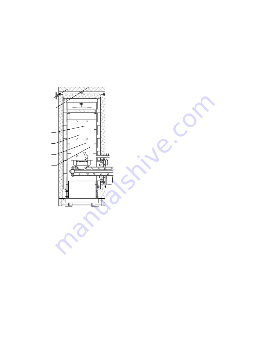
Fig. no. 24 Section of the combustion chamber of the BENEKOV S16 and S26 boiler
Fig. no. 25 Section through the combustion chamber of the BENEKOV S51 boiler
1. Feeding to the boiler
2. Screw shaft
3. Grate
4. Secondary air tube
5. Ceramic reflector (1 pc)
6. Ceramic reflector beam
1. Feeding to the boiler
2. Screw shaft
3. Grate
4. Ceramic half-ring (2 pcs)
5. Distribution of secondary air
6. Ceramic reflector (2 pc)
7. Ceramic reflector beam
1
2
3
4
5
6
Summary of Contents for S16
Page 1: ...BOILER OPERATING AND INSTALLATION INSTRUCTION MANUAL BENEKOV S16 BENEKOV S26 BENEKOV S51 ...
Page 20: ...20 Fig no 14 Boiler ash remover for S51 Fig no 15 Boiler flue gas exhaust for S16 and S26 ...
Page 27: ...27 Fig no 22 Connection dimensions of BENEKOV S26 boiler ...
Page 28: ...28 Fig no 23 Connection dimensions of BENEKOV S51 boiler ...


