4 - 61
HANDLEBAR
HANDLEBAR INSTALLATION
IMPORTANT NOTICE
Prop the bike on suitable supports so that it cannot fall.
Proceed to install, following the steps for removal in reverse
order, but taking care to observe the instructions below:
Install:
•
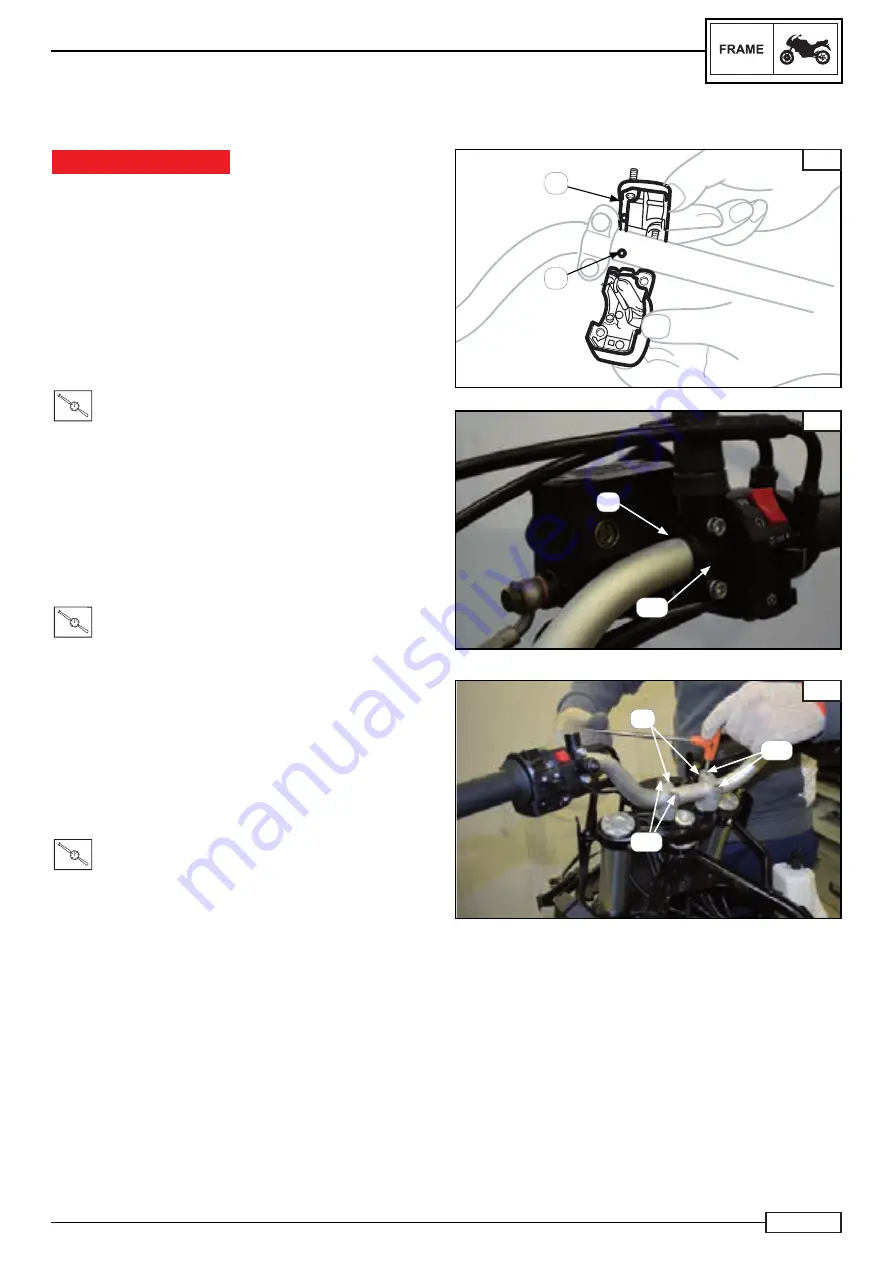
Right commutator switch (11*)
NOTE:________________________________
Align the projections (A) of the switch with the hole (B) on
the right side of the handlebar.
•
Front brake pump; tighten
to the following torque pressure:
T.R.
Torque 8 N*m
NOTE:________________________________
Install the brake pump clevis with “UP” facing upwards Fig.
F, tighten the upper screw fi rst then the lower screw.
•
Accelerator handgrip (13*)
•
accelerator control (12*)
•
fuel open cable (14*)
•
fuel close cable (15*)
•
clutch control (17*), tighten
to the following torque:
T.R.
Torque 8 N*m
•
left selector switch (10*)
•
left handgrip (8*)
•
handgrip terminal (6*)
•
right rear-view mirror (2*) and left rear-view mirror (1*)
Position the handlebar:
• handlebar
(3*)
•
U-clamp (2) of the handlebar (3*)
•
screws (1), tighten
to the following torque:
T.R.
Torque 22 N*m
NOTE:________________________________
The numbers marked (*) are a part of the spare parts table
chapter “Handlebar”.
E
A
B
F
UP
A
C
1
2
1
COPY - Moto GB - Grant Martland - grantmartland@motogb.co.uk
Summary of Contents for TRK 502
Page 6: ...1 1 1 COPY Moto GB Grant Martland grantmartland motogb co uk ...
Page 19: ...2 2 1 COPY Moto GB Grant Martland grantmartland motogb co uk ...
Page 37: ...3 1 3 COPY Moto GB Grant Martland grantmartland motogb co uk ...
Page 40: ...3 4 NOTES COPY Moto GB Grant Martland grantmartland motogb co uk ...
Page 95: ...4 1 4 COPY Moto GB Grant Martland grantmartland motogb co uk ...
Page 254: ...5 1 5 COPY Moto GB Grant Martland grantmartland motogb co uk ...
Page 345: ...6 1 6 COPY Moto GB Grant Martland grantmartland motogb co uk ...
Page 360: ...ELE 16 7 COPY Moto GB Grant Martland grantmartland motogb co uk ...


