5 - 63
C
A
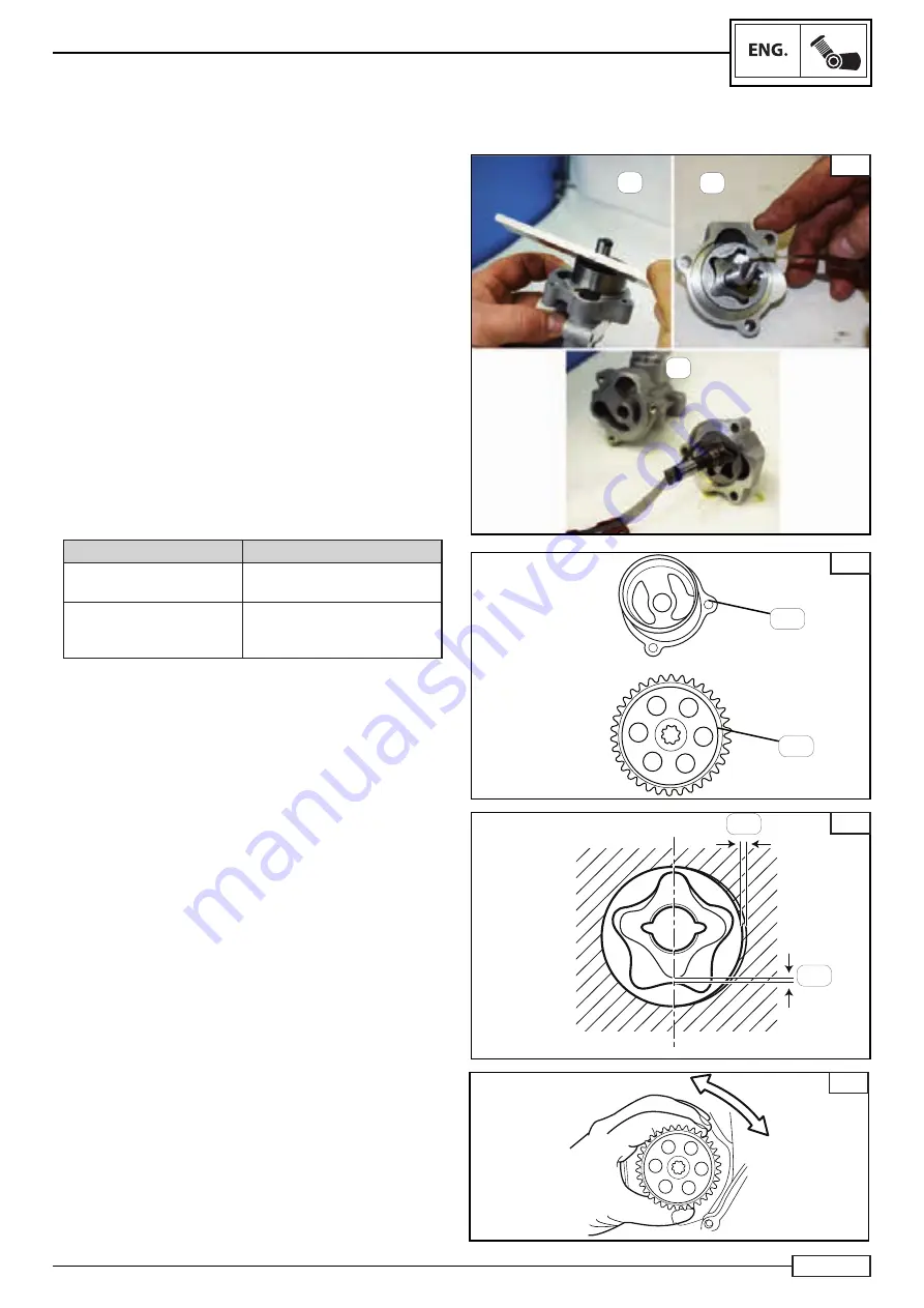
OIL PUMP REMOVAL
LUBRICATION SYSTEM
B
C
Remove:
•
the screws (9*)
•
the pump cover (6*)
•
outer rotor (10*)
•
inner rotor (11*)
• roller
(8*)
•
oil pump shaft (7*)
Check:
•
the pump body (13*) Fig. D
If there are any lines/damage/wear, replace.
•
The pump pinion (5*)
If there is any damage or wear to the gears, replace.
Measure:
•
the tolerance between the inner rotor (11*) and the outer
rotor (10*) ”C”. Fig. E and Fig. C (A)
•
the tolerance between the outer rotor (11*) and the oil pump
housing (6*) ”E”. Fig. E and Fig. C (B)
• the
fl atness of both rotors compare to the oil pump housing
(6*) “C” Fig. C.
Clearance
Tolerance
between the inner rotor
and the outer rotor ”
A”.
0.15 mm
between the outer rotor
and the oil pump housing
“
B
”
+0.06, +0.09 mm
Check:
•
oil pump operation.
Turn the pump pinion (5*) as shown in Fig. F
If the movement is not smooth, check the inner/outer rotor seat.
If there are any lines/damage, replace the
faulty part/s.
NOTE:_________________________________
This check is carried out after securing the oil pump in the
engine body and inserting the pump pinion (5*) in its seat.
NOTE:_________________________________
Numbers marked (*) are part of the spare parts table in
Chapter 5 “Lubrication circuit”.
D
E
F
13*
5*
C
D
COPY - Moto GB - Grant Martland - grantmartland@motogb.co.uk
Summary of Contents for TRK 502
Page 6: ...1 1 1 COPY Moto GB Grant Martland grantmartland motogb co uk ...
Page 19: ...2 2 1 COPY Moto GB Grant Martland grantmartland motogb co uk ...
Page 37: ...3 1 3 COPY Moto GB Grant Martland grantmartland motogb co uk ...
Page 40: ...3 4 NOTES COPY Moto GB Grant Martland grantmartland motogb co uk ...
Page 95: ...4 1 4 COPY Moto GB Grant Martland grantmartland motogb co uk ...
Page 254: ...5 1 5 COPY Moto GB Grant Martland grantmartland motogb co uk ...
Page 345: ...6 1 6 COPY Moto GB Grant Martland grantmartland motogb co uk ...
Page 360: ...ELE 16 7 COPY Moto GB Grant Martland grantmartland motogb co uk ...


