5 - 70
GEAR BOX ASSEMBLY
GEAR BOX
Measure:
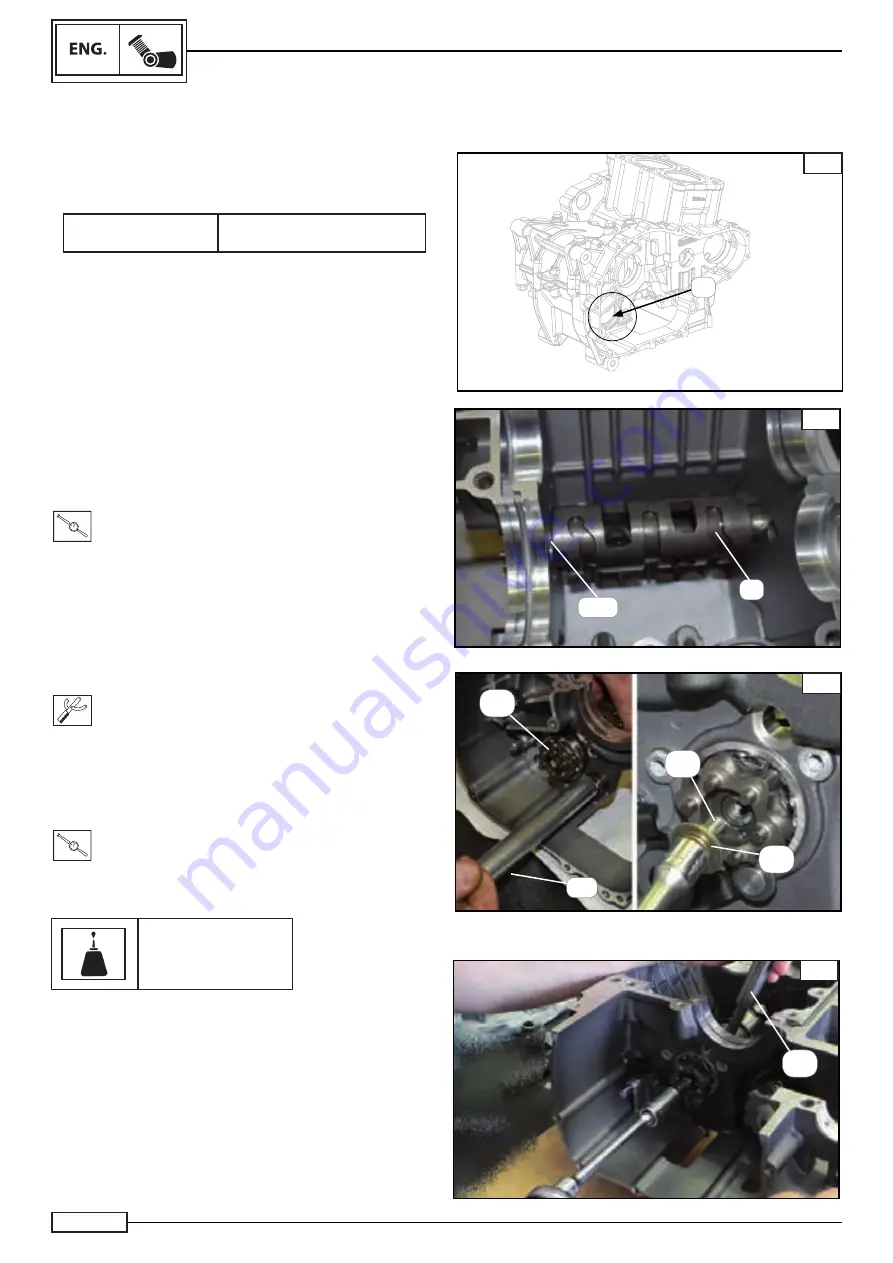
Use a specifi c gauge to check the size of the hole (1) in the top
right casing Fig. A.
Housing port
desmodronic
size: Ø 47 (0,+0.022) mm
If outside specifi cations, replace the bottom casing.
Check:
•
The grooving on the desmodromic shaft (9) Fig. B.
In the presence of damage/lines/signs of wear, replace the who-
le desmodromic shaft.
Assemble:
•
the desmodronic (9*) inside the casing
•
nstall the bearing (11*) Fig. B
T.R.
Torque 12 N*
NOTE:_________________________________
Numbers marked (*) are part of the spare parts table in
Chapter 5 “Gears”.
Assemble:
•
the gear drum (14*)
using the special tool
(**)
Fig. C
(**) Gear selector drum assembly tool
Code:0320097051000
• washer
(15*)
•
screw (16*) Fig. C to the following torque:
T.R.
Torque 12 N*m
Use Loctite
Loctite 243
NOTE:_________________________________
To tighten the screw (16*), use an aluminium pad (1) to keep
the desmodronic in place Fig. D.
A
B
9*
11*
1
C
(**)
14*
D
1
15*
16*
COPY - Moto GB - Grant Martland - grantmartland@motogb.co.uk
Summary of Contents for TRK 502
Page 6: ...1 1 1 COPY Moto GB Grant Martland grantmartland motogb co uk ...
Page 19: ...2 2 1 COPY Moto GB Grant Martland grantmartland motogb co uk ...
Page 37: ...3 1 3 COPY Moto GB Grant Martland grantmartland motogb co uk ...
Page 40: ...3 4 NOTES COPY Moto GB Grant Martland grantmartland motogb co uk ...
Page 95: ...4 1 4 COPY Moto GB Grant Martland grantmartland motogb co uk ...
Page 254: ...5 1 5 COPY Moto GB Grant Martland grantmartland motogb co uk ...
Page 345: ...6 1 6 COPY Moto GB Grant Martland grantmartland motogb co uk ...
Page 360: ...ELE 16 7 COPY Moto GB Grant Martland grantmartland motogb co uk ...


